

Autor: AEGIS
US Motors Inverter Duty Hazardous Location Motors with AEGIS®
U.S. MOTORS® hazardous location motors are designed for use on pumps, compressors, fans, conveyors and tools in potentially explosive environments. These motors are built to prevent ignition outside the motor by containing sparks, flashing, and explosions inside the motor casing. They are ideal for many applications in oil and gas, industrial paint and coating, and grain processing operations, to name just a few.
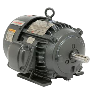 US Motors hazardous location motors are all NEMA Premium® Efficiency with a 1.0 or 1.15 service factor, and meet other NEMA standard requirements. For variable frequency drives, there are also lines of hazardous location Inverter Duty motors. Inverter Duty motors include protection against the side effects of VFD control: electrical damage to the stator windings and bearings.
So Inverter Duty US Motors include an Inverter Grade® insulation system to protect the windings. That is, additional phase paper between coils, extra bracing on end turns, and Insulife 2000 insulation treatment.
The bearings are protected by an internal AEGIS® Shaft Grounding Ring. Larger motors, over 400 NEMA frame, also have bearing insulation at the non-drive end.
With all of these protections in place, US Motors Inverter Duty hazardous location motors are prepared to run safely AND reliably wherever they’re installed.
The factory-installed AEGIS Rings also come with a 2-year extended warranty against bearing fluting damage. No other form of protection against VFD-caused bearing damage offers a warranty like this.
 To learn more about AEGIS shaft grounding and best practices for electrical bearing protection, sign up for a training. We offer monthly live training webinars, and we can also visit your facility to review your exact application.
Electrical Bearing Protection Q&A – Part 18
Part 18 in a series of questions and answers from our Q&A webinars.
Q1. How are AEGIS Rings applied to submersible pump motors?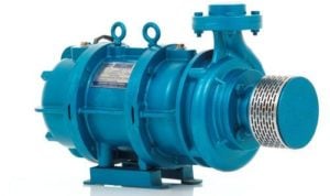
A1. It depends on the manufacturer and motor. Some motor designs have the bearings in an oil bath. That’s a problem for now. We are developing grounding rings that can tolerate higher grease and oil levels.
But for now, you want any AEGIS ring to be running in a dry environment. We have grounding rings in plenty of submersible pumps. Just not in the oil-filled design.
Q2. What value of shaft voltage could be acceptable?
A2. We usually see zero to 35 V before shaft grounding. Say it’s 15 V. Then you put on an AEGIS ring, add a braided grounding strap, and put colloidal silver on the shaft. The shaft voltage will usually decrease to under 1 V peak. This is about as safe as it gets, so we use one volt as a benchmark.
But we can’t always get the shaft voltage so low. What you’re most looking for is a big reduction. We had a situation recently with a shaft with 45-50 V on it. Our best practices brought it down to 3 V. So you may not get shaft voltage down to zero, and it may not be perfect. But decreased shaft voltage will improve things, and we’ll work with you on whatever you’ve got.
Q3. You’ve said motors over 100 hp/75 kW need, along with AEGIS, an insulated bearing. But those are expensive and difficult to install. Can you just use two AEGIS rings instead, one at each end of the motor?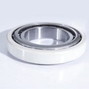
A3. You don’t want to do that. That seems like a good idea, and we actually used to recommend two AEGIS rings. The logic was that the rings would offer much less resistance than the (ordinary) bearings, so the circulating current would only move through the rings. But we quickly found that it doesn’t work as planned; current still circulated through the bearings. Which is surprising but true.
One insulated bearing opposite the AEGIS ring seems necessary to stop the circulating current. Lots of motor manufacturers are now installing insulated bearings at the non-drive end of larger motors. They do this with motors of 75 to 125 hp and up.
As for the expense: Yes, it’s expensive. But not as expensive as bearing failure. Say you’ve got a 200 hp motor, with one SGR, on a drive. The motor is protected against shaft voltage discharge but not circulating current. So a bearing may fail. If that happens, it’ll cost $5,000 to repair it. Plus, you’ll need to ship it wherever for repair, plus you’ll have the cost of downtime. Add an insulated bearing costs a lot less than the repair and downtime, by far.
AEGIS Rings also come with a 2-year extended warranty against bearing fluting damage. No other form of protection against VFD-caused bearing damage offers a warranty like this.
To learn more about AEGIS shaft grounding and best practices for electrical bearing protection, sign up for a training. We offer monthly live training webinars, and – pandemic restrictions permitting – we can also visit your facility to review your exact application.
Vertical HOLLOSHAFT Motors with AEGIS
US Motors is a leader in the vertical hollow shaft motor market. Their HOLLOSHAFT® Motors are ideal for use on turbine, mix flow, propeller, and other pumps. And now, all of their Inverter Duty Weather Protected Type I (WPI) and CORRO-DUTY® HOLLOSHAFT motors include AEGIS® Shaft Grounding Rings for electrical bearing protection.
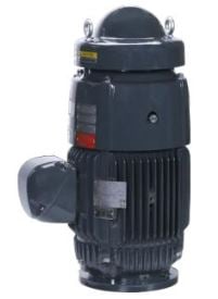 WPI HOLLOSHAFT motors are constructed to minimize ingress of rain and snow, as well as dust and dirt. And their ventilation system optimizes cooling of the thrust bearing and electrical components. CORRO-DUTY motors have TEFC frames to prevent ingress and corrosion-resistant paint and hardware for extremely harsh environments.
Inverter duty motors are designed to resist the side effects of variable frequency drive (VFD) control. VFDs can cause electrical damage to both the stator windings and the bearings of the motors they control. To protect the windings, these inverter duty motors include Class H Inverter Grade® insulation.
VFDs produce voltage on the shafts of the motors they control, and this voltage can cause arcing through the bearings. In larger motors, over 100 hp, drives also produce high-frequency circulating currents that go through both bearings at once. All inverter duty WPI and CORRO-DUTY HOLLOSHAFT motors include an AEGIS Shaft Grounding Ring mounted inside, to discharge shaft voltage safely. And those over 100 hp also include an insulated thrust bearing to block circulating currents.
AEGIS Rings also come with a 2-year extended warranty against bearing fluting damage. No other form of protection against VFD-caused bearing damage offers a warranty like this.
To learn more about AEGIS shaft grounding and best practices for electrical bearing protection, sign up for a training. We offer monthly live training webinars, and we can also visit your facility to review your exact application.
Electrical Bearing Protection Q&A – Part 17
Part 17 in a series of questions and answers from our Q&A webinars.
Q1. What is the magnitude of the current coming off the shaft? Is it hazardous?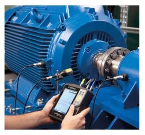
A1. No need to worry. If you put your finger on the running shaft of a motor on a drive, with or without an AEGIS ring, you wouldn’t feel anything. It’s not like licking a 9V battery.
Whether it’s moving through a bearing or a grounding ring, current from the shaft comes in pulses. Most of the time, nothing is happening, and then there’s a sudden tiny spike of current, and then back to zero. Without shaft grounding, you might have spikes of 500 milliamps that last for tens of nanoseconds. With shaft grounding, the current spikes will be much smaller, but more frequent. Either way, most of the time nothing is happening, and when the current does flow, it’s very brief. So the average (rms) current from the shaft is very small.
When shaft voltage discharges through a bearing, it creates a tiny arc. Although the total energy in this arc is small, the area where it’s released is also small. The energy density is high enough to damage the bearing. If you put your finger on the shaft (mind the keyway!), then capacitive current could flow across your skin to the ground. But this current’s energy would be spread all across your skin, so the energy density would be too low for you to even notice.
Q2. As the shaft turns, the fibers overlap it in the direction of rotation. If the motor were bidirectional, what effect would that have?
A2. There are many systems with a motor working both clockwise and counterclockwise. Cranes and winches are a couple of examples. And this is no problem. Our testing indicates there’s no limit to the number of reversals AEGIS microfibers can tolerate.
There are a couple of reasons they stand up so well to reversal. AEGIS fibers are pretty densely packed into the ring. Think about trees in a forest. An isolated tree might get blown over by whipsawing wind, but a whole forest can survive stronger winds. The AEGIS Ring also has a Fiberlock Channel in it that locks the fibers into place.
Between the fiber density and the fiber lock, Shaft Grounding Rings tolerate reversals without any problem.
Q3. How do you safely place a scope lead on a rotating motor shaft?
A3. With caution. That’s the main thing. You want to keep your hands away from any fast-moving objects – motor shafts, belts, fans…
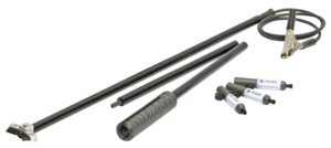 Some of the accessories from the SVP-KIT-9100MB: shaft grounding simulator with alligator clamp lead, oscilloscope probe holder and wand, and shaft voltage probe tips.
We sell an an accessory kit for shaft voltage testing, SVP-KIT-9100MB. The kit includes a wand that you can use to touch a probe tip or shaft grounding simulator to the motor shaft. You don’t technically need the wand to safely extend your reach. We have had customers jury-rig their solutions, ranging from custom-machined rods to duct tape on broomsticks. We don’t exactly endorse broomsticks as shaft voltage testing accessories, but if it works…
It’s actually pretty easy to touch the probe tip to the shaft. It’s a little trickier to connect the probe ground clamp – it’s a little alligator clip on about a four-inch (10 cm) cable. What usually works is to connect a larger alligator clamp to a lug or piece of bare metal on the motor frame. Then you connect the ground clamp to the larger clamp’s wire. The accessory kit I mentioned includes a larger alligator clamp for this.
To learn more about AEGIS shaft grounding and best practices for electrical bearing protection, sign up for a training. We offer monthly live training webinars, and – pandemic restrictions permitting – we can also visit your facility to review your exact application.
High Proof Shaft Grounding: AEGIS Rings in an Ethanol Plant
In early 2017, at Red Trail Energy’s ethanol plant in North Dakota, several large motors’ ball bearings were failing much sooner than they should. Replacing motor bearings isn’t cheap. But for a production plant, the actual cost of repair is a drop in the bottle. What really hurts is the downtime from repair causing lost production. And lost revenue.

The plant manager soon had enough of these frequent interruptions and called in a grounding system specialist to troubleshoot the three problem motors.
 The plant’s 400 hp HVAC motor
Scott Fisher, at Sustainable Grounding Systems, has a long history with Red Trail Energy. He arrived at the plant in May 2017 and took initial readings from three problematic motors: two centrifuge motors (30 and 150 hp) and one 400 hp fan motor. He confirmed that the bearings in these motors had premature damage, well beyond the expected ordinary wear and tear.
The leading suspect? Stray voltage from variable frequency drives. VFDs cause voltage to build upon the shafts of the motors they control. That voltage tends to discharge through the path of least resistance: the bearings. This shaft voltage discharge causes the bearings to wear, and fail, prematurely.
Fisher’s solution was to install AEGIS® Shaft Grounding Rings. Following AEGIS best practices, he installed an AEGIS SGR on each centrifuge motor, and an AEGIS PRO Ring on the 400 hp motor.
The follow-up shaft voltage readings from the motors showed significant improvement. Measurements as high as 19 volts dropped to less than 1.3 volts, which is too low to cause premature damage to the bearings.
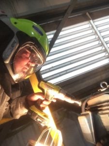 Scott Fisher installs an SGR on one of the centrifuge motors
The curious reader might wonder how permanent the AEGIS solution was. It’s a good question! And the good answer is that now, almost four years later, AEGIS is still working. These motors have yet to fail again due to electrical bearing damage. Over the past four years, AEGIS rings have saved this plant tens of thousands, if not hundreds of thousands, of dollars. That’s a pretty good return on investment!
This blogpost is adapted from a story published at ChemicalProcessing.com
AEGIS Rings also come with a 2-year extended warranty against bearing fluting damage. No other form of protection against VFD-caused bearing damage offers a warranty like this.
To learn more about AEGIS shaft grounding and best practices for electrical bearing protection, sign up for a training. We offer monthly live training webinars, and we can also visit your facility to review your exact application.
Electrical Bearing Protection Q&A – Part 16
Part 16 in a series of questions and answers from our Q&A webinars.
Q1. Can we diagnose the presence of shaft voltage based on vibration analysis?
A1. You can detect electrical bearing damage with vibration analysis, but only after it’s occurred. You need an oscilloscope to measure shaft voltage in some way. The usual way is to capture the shaft voltage waveform to look for discharges with an ordinary oscilloscope. Or you can use a more specialized tool like the Beppe which automatically detects and counts discharges.
Q2. How can you diagnose whether a motor bearing needs to be protected, and what would you see on a bearing that failed due to electrical damage?
A2. Shaft voltage testing, by whatever means, will show you whether a bearing is at risk. In some cases, you can also use an electrical discharge detector. In our experience though, discharge detectors don’t work well with small motors. In either case, the testing is all done online, while the motor is running.
If the bearing has already failed, you will need to cut it, examine the grease, and see what the balls and inside of the raceways look like. In case of electrical damage, the grease will usually be black from charring and contamination with metal particles. And the race will have visible damage ranging from frosting to fluting. Both are easy to see. Frosting shows as a matte band, very distinct against the mirror-smooth finish of the rest of the race. And fluting shows as regular striping occurring in a frosted band. In either case, the rolling elements will typically also be frosted.
Q3. What kind of oscilloscope do I need to measure shaft voltage?
A3. Like TVs or VCRs (remember those?), oscilloscopes all work pretty much the same. The one catch is that you need a scope with at least 100 MHz bandwidth. Shaft voltage buildup, and especially discharge, are fast phenomena. A scope’s bandwidth is a measure of its ability to measure high-speed/high-frequency events.
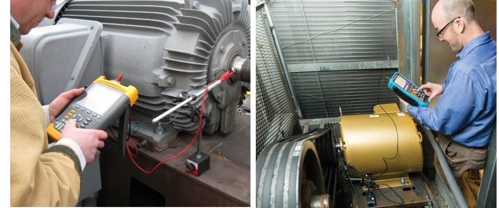
The higher the bandwidth, the more accurate at low timescales/high frequencies. We’ve found that 100 MHz is enough. Higher bandwidth is good, but you don’t need to go out and buy a 500 MHz scope when 100 MHz is fine. You will need some type of special probe tip. We offer the SVP-TIP-9100 3-pack of probe tips, which fit our own and some Fluke probes. We also offer a 10:1 probe plus tip combo pack, the AEGIS-SVP-510. The probe has a BNC connector so you can use it with any oscilloscope with BNC ports. You can see all of our shaft voltage testing accessories here.
To learn more about AEGIS shaft grounding and best practices for electrical bearing protection, sign up for a training. We offer monthly live training webinars, and – pandemic restrictions permitting – we can also visit your facility to review your exact application.
Electrical Bearing Protection Q&A Part 15
Part 15 in a series of questions and answers from our Q&A webinars.
Q1: I know AEGIS® Rings protect motor bearings from electrical damage. But what about the load? Does the equipment being driven need protection, too?
A1: If you have a motor on a drive, and induced shaft voltage, that voltage can discharge either through the motor’s bearings or the loads. Be it a pump, gearbox, or whatever. The vast majority of the time, this will take care of it:
- Install one shaft grounding ring on the motor. This will protect the motor and load bearings from shaft voltage discharge.
- Bond the motor frame to the load frame with a high-frequency grounding strap. This will protect the motor and load bearings from possible rotor ground current.
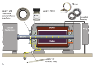
- If the motor is over 100 hp/75 kW, you should also insulate the motor bearing opposite the AEGIS ring. This will block potential high-frequency circulating current.
To some extent, you can replace #2 and #3 with an inductive core, but we have not exhaustively tested this. We have thoroughly tested the practices above, and we know they work. We do occasionally see people put one grounding ring on the motor and another on the load, but this isn’t usually necessary if you use a grounding strap between the motor and load.
Q2. Would it be better to spec a motor with a grounding ring if a VFD is specified to control the motor?
A2. Yes, but there are some complications here. Sometimes you don’t know if you’ll be using a drive; sometimes it’s determined after the fact; sometimes it’s decided at the last minute that drives will be used, but no provision is made for shaft grounding.
There’s also a fairly good chance that a motor’s not specified to go on a drive, but it will – a year or five down the road – end up on a drive.
In all of those cases, if you get a motor with AEGIS, then it will be protected in the event that it does end up on a drive, either from the start of a few years down the line.
Q3. Should AEGIS be installed in all motors, regardless of whether they’re supplied by a VFD?
A3. If the motor’s not on a VFD, you’d need some other condition to  require an AEGIS ring. If your application involves a lot of static electricity, then it would make sense to install AEGIS. If you’re rolling mylar film or vinyl flooring, for instance, the material will pick up static and that can discharge through the bearings of the rollers or the motors driving the conveyors.
It certainly simplifies things to be prepared so you don’t have unexpected failures. But if you just have a motor, not on a drive, with no static problem, an AEGIS ring won’t help, unless you add a drive in the future, as discussed above.
AEGIS Rings come with a 2-year extended warranty against bearing fluting damage. No other form of protection against VFD-caused bearing damage offers a warranty like this.
To learn more about AEGIS shaft grounding and best practices for electrical bearing protection, sign up for a training. We offer monthly live training webinars, and – pandemic restrictions permitting – we can also visit your facility to review your exact application.
Best Practices for Bearing Protection
In our last post, we described how VFDs cause electrical bearing damage. So, how do you protect motors from this damage?
Capacitive EDM currents come about because of the shaft voltage, the voltage difference between the rotor and the frame. This voltage difference drives electrons through the bearings. But you can short circuit this effect and prevent EDM current by providing an alternative, low-resistance path from shaft to frame. AEGIS® Shaft Grounding Rings provide such a path, allowing electrons to flow harmlessly between the shaft and frame.
For low-voltage motors (up to 100 hp/75 kW), the best practice is to install an AEGIS SGR to discharge capacitively induced shaft voltage. The ring can be installed internally or externally, at either the drive end or non-drive end of the motor.
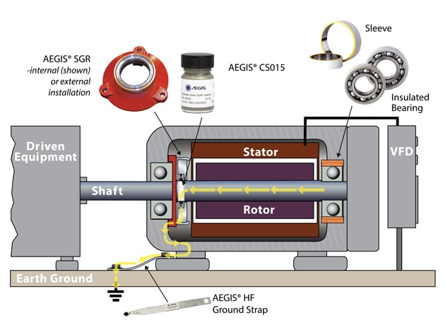 For motors greater than 100 hp/75 kW, capacitive EDM current will still be present, but now high-frequency circulating currents will occur as well. The best way to prevent HF circulating currents is to interrupt them with insulation or isolation of the bearing at the opposite end from the AEGIS ring. So for motors between 100 and 500 hp (75-375 kW), the best practice is to install an AEGIS SGR on the drive end, and isolate the bearing on the non-drive end to disrupt circulating current. This isolation can be done with an insulating sleeve or coating, or an insulated ceramic or hybrid bearing.
For low-voltage motors greater than 500 hp/375 kW, and medium-voltage motors, use an AEGIS PRO Ring instead of an SGR.
For motors with both bearings insulated, the driven equipment’s bearings are at risk. So we recommend installing the appropriate AEGIS ring (SGR or PRO) on the drive end. This will keep induced shaft voltage from discharging through the equipment’s bearings.
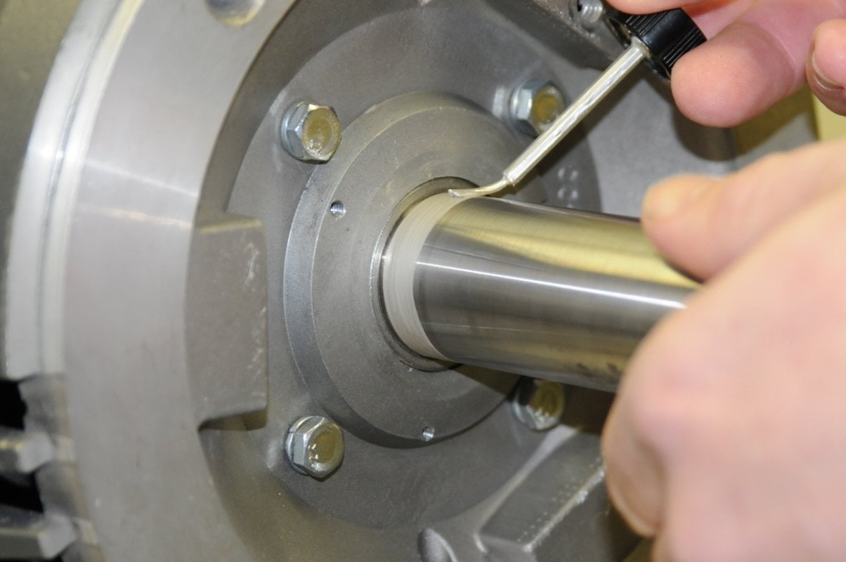 Regardless of the type of AEGIS ring or where you install it, we also recommend that you apply AEGIS Colloidal Silver shaft coating to the motor shaft in the area where the ring’s conductive fibers will contact it. Colloidal Silver improves the shaft surface’s conductivity and helps the AEGIS ring work.
AEGIS Rings also come with a 2-year extended warranty against bearing fluting damage. No other form of protection against VFD-caused bearing damage offers a warranty like this.
To learn more about AEGIS shaft grounding and best practices for electrical bearing protection, sign up for a training. We offer monthly live training webinars, and – pandemic restrictions permitting – we can also visit your facility to review your exact application.
Electrical Bearing Protection Q&A Part 14
Part 14 in a series of questions and answers from our Q&A webinars.
Q1: Does the discharge current oscillate polarity? I often see shaft voltage plots with what looks like positive and negative discharge spikes.
A1: Short answer: yes. We focus on the «positive» discharges (center in the figure) because it’s intuitive to think of something unstable «building up» and then crashing back to the ground. In fact the motor shaft and rotor can be positive or negatively charged relative to the frame. Regardless of the shaft voltage polarity, damage will be done if it arcs through the bearings.
Q2. Is the grounding ring appropriate for a dusty environment like a mine, or could accumulated dust interfere with its function?
A2: AEGIS® rings have been used inside plenty of mines and paper mills. These are some of the dustiest, dirtiest environments on earth.
The rings are resilient against moderate amounts of dust. Their fibers tend to sweep the motor shaft clean. In dirtier environments, you can also slip an O ring up the shaft, or use a slinger or other protective cover. If that’s not enough, the AEGIS ring can always be installed inside the motor, either by the manufacturer or by a motor repair contractor.
Q3. What are the pros and cons of AEGIS rings compared with inductive absorbers?
A3: We answered a related question in our last Q&A about inductive filters inside of drives. In brief, AEGIS rings and inductive absorbers do different things, and protect against different things.
There are three ways VFDs can damage motor bearings: #1, shaft voltage discharge current, #2 high-frequency circulating current, and #3 rotor ground current. Shaft voltage discharge is a problem in all motors on drives. It is caused by the common mode voltage of the drive’s output. Circulating currents are only a problem in larger motors, over 100 hp (75 kW), and rotor ground current is a problem when the motor is not well-grounded. These two are caused by common mode current in the drive’s ouptut.
AEGIS rings primarily protect against shaft voltage discharge, #1. Inductive cores protect against #2 and #3. These chokes reduce peak common mode current, but they barely affect common mode voltage. But the common mode voltage is what produces the shaft voltage. So while inductive absorbers reduce bearing currents #2 and #3, they do not do not protect against #1.
This is clear in the shaft voltage readings below. On the left is a motor without an inductive absorber. The shaft voltage (yellow) builds up and then collapses. That collapse means an arc through the bearing. On the right is a motor with an inductive absorber. The shaft voltage builds up and again, discharges by arcing through the bearing.
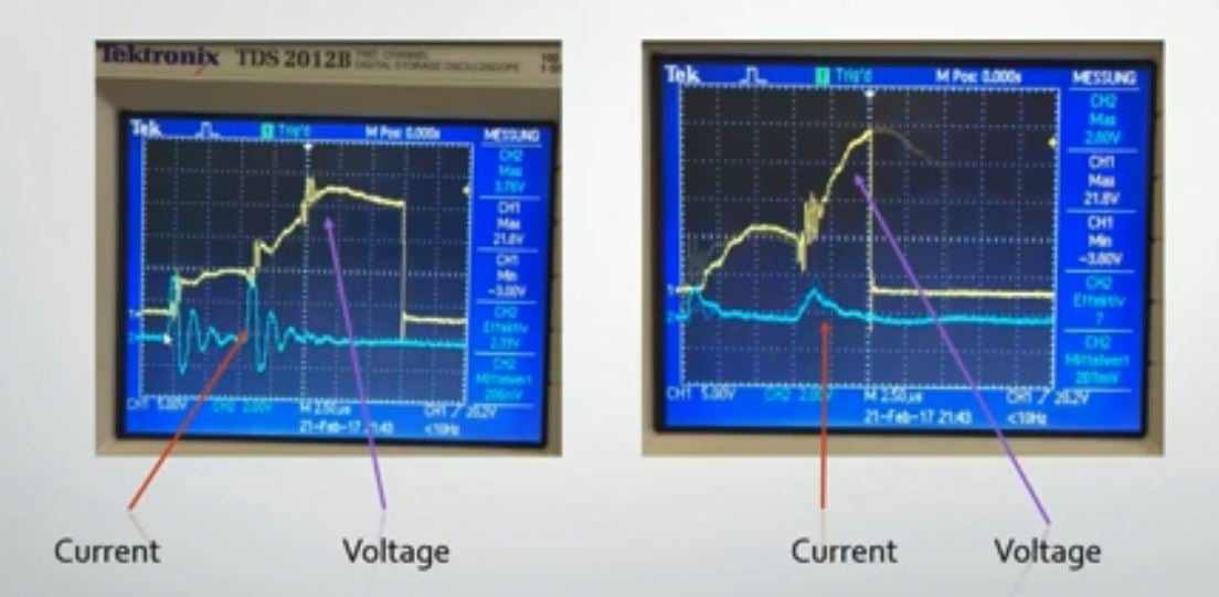 Shaft voltage without (left) and with (right) an inductive filter. Shaft voltage builds up and arcs through the bearing either way.
Common mode chokes or inductive absorbers cannot protect against shaft voltage discharge current. If you use chokes, you need a second type of protection against bearing current #1. There are many options, but an AEGIS Shaft Grounding Ring is usually the most practical.
AEGIS Rings also come with a 2-year extended warranty against bearing fluting damage. No other form of protection against VFD-caused bearing damage offers a warranty like this.
To learn more about AEGIS shaft grounding and best practices for electrical bearing protection, sign up for a training. We offer monthly live training webinars, and – pandemic restrictions permitting – we can also visit your facility to review your exact application.
How Do VFDs Cause Bearing Damage?
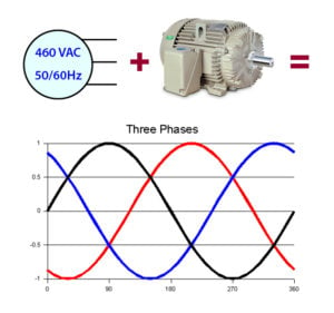 Electric induction motors were designed to be operated on 3-phase sine wave power. This input power is balanced, meaning that the three voltage phases cancel each other out (sum to zero). So when phase A is at +460V, phases B & C will be at -230V. (+460V – 230V – 230V = 0V.) The common mode voltage is the average of the three phases. Since the phases sum to zero, the common mode voltage is also zero when power is properly balanced. When the common mode voltage is zero, the bearings are not usually at risk of electrical bearing damage (except for very large motors, over 500 frame).
But when motors are operated by variable frequency drives (VFDs), the transistors in the drive convert pure sine wave power to a series of positive and negative pulses. Consequently, the input voltage to the motor is never balanced. Instead of each phase voltage being a smooth sine wave, they switch rapidly from positive to zero to negative and back. The phases no longer cancel out, and instead of being zero, the common mode voltage is usually a «square wave» or a «6-step» voltage waveform.
This nonzero common mode voltage in a motor’s stator windings causes motor bearings to «charge up» like a capacitor. For example, suppose that at one moment, the common mode voltage is positive inside the stator windings. This positive common mode voltage induces a positive voltage on the rotor through capacitive coupling. There is also coupling between the windings and the motor frame. But the frame is grounded, so it remains neutral.
With the rotor now positive and the frame still neutral, there is a voltage difference across the motor’s bearings between the rotating shaft and motor’s grounded frame. This voltage across the bearings is usually referred to as shaft voltage. The bearings are full of electrically insulating (dielectric) grease, which forms a non-conductive film between the balls and race walls. So electrical current cannot normally flow through the bearings. This is exactly like a capacitor: two conductors separated by a non-conductive dielectric. If you apply a dc voltage to a capacitor, it will «charge up,» and store energy, but not let appreciable current flow through… unless the dielectric breaks down.
Every capacitor has a breakdown voltage*; a voltage above which the insulator breaks down and allows a burst of current to flow all at once. This is just like lightning: When the voltage between a cloud and the ground gets big enough, the air – normally a good insulator – becomes ionized and suddenly becomes conductive. The result is a rapid discharge: charge flows rapidly through the now-conductive air with the often-destructive release of stored energy. After discharge, the voltage across the capacitor will be zero (or at least much lower).
Now back to the motor: If the shaft voltage builds up high enough, it will discharge by arcing through the bearing: Electrons will leap through the bearing like a miniature lightning bolt, and destructively release the energy that was stored in the bearing’s capacitance. This arc is called a capacitive discharge current, and the damage it does to bearing surfaces is called EDM (electrical discharge machining). Capacitive EDM currents can occur in all motors run on VFDs, regardless of their size.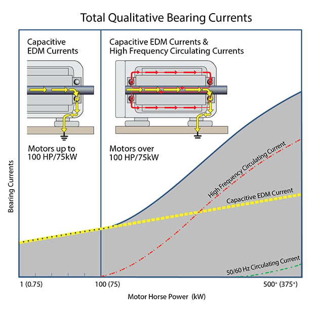
A second form of bearing current produced by VFDs — high frequency (HF) circulating currents — results from a high-frequency magnetic flux produced by common mode current (the sum of the currents flowing in each of the three phases). Just like common mode voltage, common mode current is zero when the power to a motor is balanced, but not when the motor is on a drive. HF circulating current is produced by the imbalanced magnetic flux of the common mode current. Circulating current consists of electrons arcing from the shaft through one bearing, running down the frame, and arcing through the other bearing back to the shaft. The frequency range for these currents is in the kHz or MHz. The size of these currents, and the damage they do, depends on motor size. They first become a problem in motors above 100 HP (75 kW). In general, the larger the motor, the greater the damage they cause.
Both capacitive discharge currents and HF circulating currents damage the bearings. Because the bearing lubricant is insulating, these currents can only flow by arcing through the grease. This both degrades the grease and damages the surfaces inside the bearing. This surface damage is directly caused by the electrical arcing through the bearing. Each arc creates a pit, a tiny molten crater where it strikes.
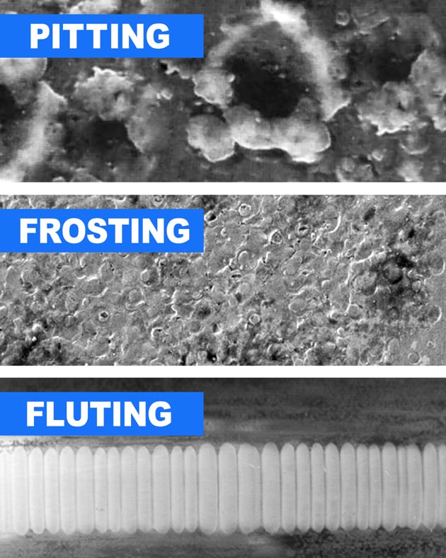
As the pits accumulate, they lead to visible frosting, and eventually to fluting (washboard-like ridges in the bearing race). As bearings degrade, friction increases, leading to noise, further deterioration of the grease, and the likelihood of total bearing failure and costly unplanned downtime. In fact, this entire process can take place in as little as 3 months!
To learn how to prevent this electrical bearing damage from VFDs, read the companion article, Bearing Protection Best Practices
*For a bearing, the exact breakdown voltage will depend on RPM, temperature, loading, state of lubrication, state of wear, and many other variables. In practice, a bearing’s breakdown voltage is unpredictable, but measured shaft voltages under up to 5V peak (10V peak-peak) are considered safe. Higher shaft voltages are likely to cause discharge.
AEGIS Rings also come with a 2-year extended warranty against bearing fluting damage. No other form of protection against VFD-caused bearing damage offers a warranty like this.
To learn more about AEGIS shaft grounding and best practices for electrical bearing protection, sign up for a training. We offer monthly live training webinars, and we can also visit your facility to review your exact application.
FAQ
Q1. How can electric motor users determine whether their electric motors are at risk of bearing damage from VFDs?
A1. The best way to tell if a motor is at risk of electrical bearing damage is to measure the shaft voltage. You can find details here, and for more detail, see the AEGIS Bearing Protection Handbook. There is no hard and fast rule, but if the shaft voltage is above 5V peak, the motor is probably at risk of electrical bearing damage.
Q2. Are there specific measures or technologies available to mitigate the risk of bearing damage caused by VFDs?
A2. Yes, these are detailed in our companion blogpost on Bearing Protection Best Practices, and in our Bearing Protection Handbook. Briefly, all motors on drives should be equipped with an AEGIS ring, and those over 100hp/75 kW should have some type of insulation for the bearing at the opposite end from the grounding ring. Proper grounding and bonding practices should be observed in all motor installations, with or without a VFD.
Q3. Is there a recommended frequency or schedule for inspecting and maintaining motor bearings to prevent or detect damage early on?
A3. There is no hard and fast rule, but motor users should definitely set up a proactive maintenance schedule. The frequency of inspections will vary depending on factors like the criticality of the motors. Typically, motor bearings should be inspected at regular intervals, ranging from monthly to annually, depending on the application and environment. Regular maintenance activities may include visual inspections, vibration analysis, lubrication checks, temperature monitoring, and shaft voltage testing.