

Auteur/autrice : AEGIS
How to Choose a Shaft Grounding Ring – Part 3
So far, we have covered clamp-on and conductive epoxy mounting for external installation and bolt-through and press-fit mounting for installing an AEGIS ring inside a motor. This time, we will cover our universal mounting kits.
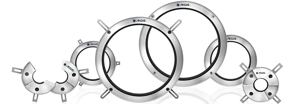
When to Choose the AEGIS uKit
The fifth and most popular style of AEGIS ring is the uKIT, which is available in solid and split builds. uKITs include a grounding ring and four different sets of mounting brackets. Those brackets allow you to position the SGR at the working diameter of the shaft. (The working diameter is the U dimension for NEMA frame motors, or D dimension for IEC frame.)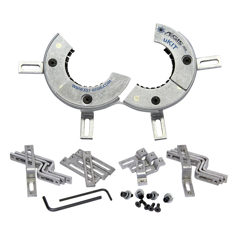
That means that all you need to know to choose a uKIT is the motor’s frame size. There’s no need to measure the shaft if it’s wider than the working diameter where the ring would sit. This makes it much easier to size a uKIT than one of the other mounting styles. AEGIS uKITs are available for NEMA frame sizes from 56 to 449T, and IEC frames 100L to to 355M.
The mounting brackets themselves can be attached with bolts, requiring a drill and tap, or with conductive epoxy (EP2400). A split uKIT with conductive epoxy is arguably the easiest AEGIS ring to install.
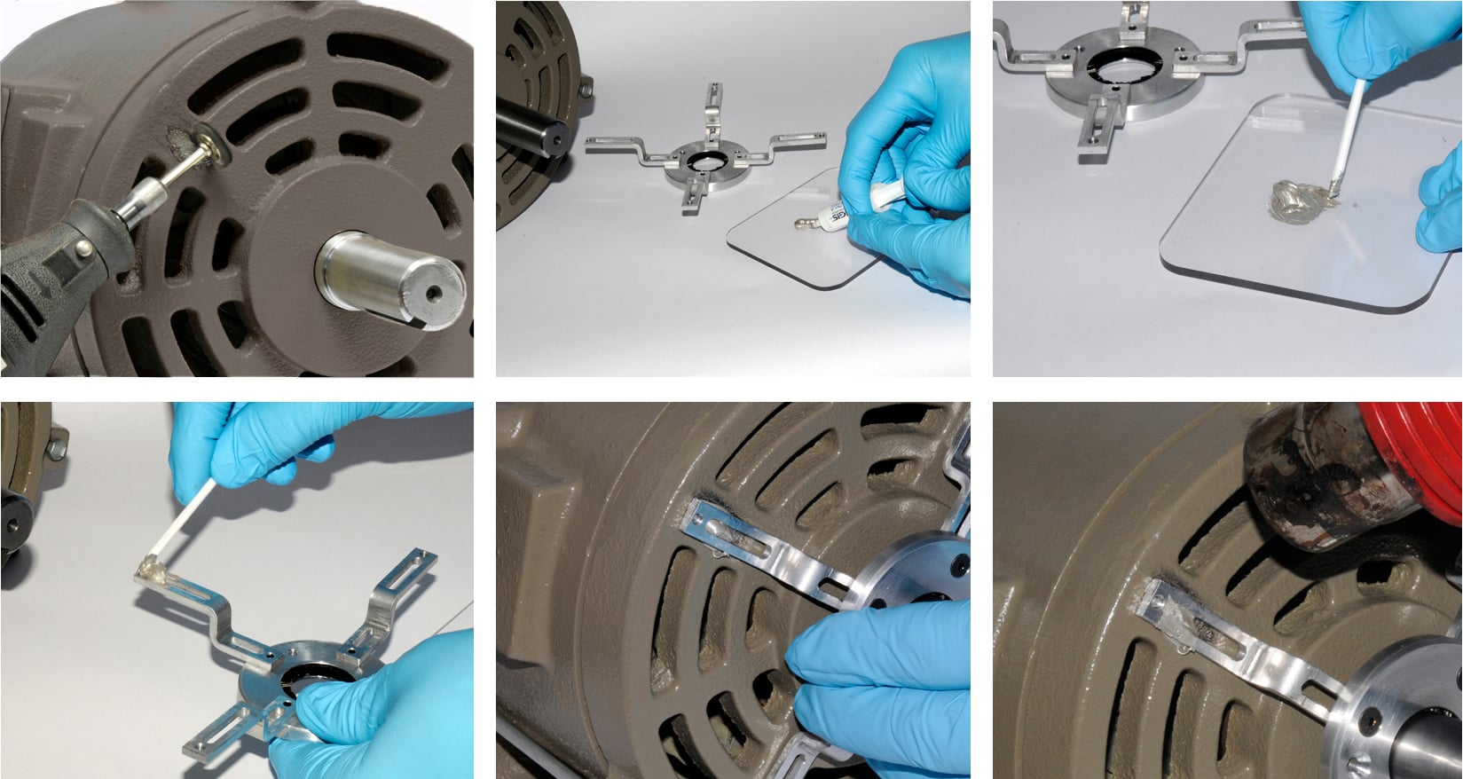
There are only a few cases where a uKIT wouldn’t work. Close-coupled pump motors (NEMA frames ending JM or JP) may not have room for a uKIT with mounting brackets between the motor and pump. In this case, you would want a clamp-on or bolt-through ring, either at the drive end or the opposite end (between the motor frame and the cooling fan). 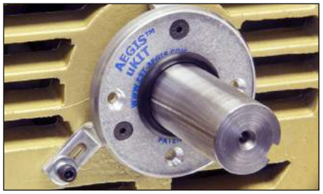
And uKITs can’t be installed inside the motor, as they are sized for the working diameter of the shaft, not the internal diameter. So in very wet or dirty environments, you would prefer to install a bolt-through SGR inside the motor, rather than a uKIT outside. This can be mitigated somewhat by sliding an O ring up the shaft to guard the fibers, as shown.
AEGIS Shaft Grounding Rings also have a 2-year extended warranty against bearing fluting damage. No other form of shaft grounding offers a warranty like this.
To learn more about AEGIS shaft grounding and best practices for electrical bearing protection – for motors and generators – sign up for a training. We offer monthly live training webinars, and we can also visit your facility to review your exact application.
How to Choose a Shaft Grounding Ring – Part 2
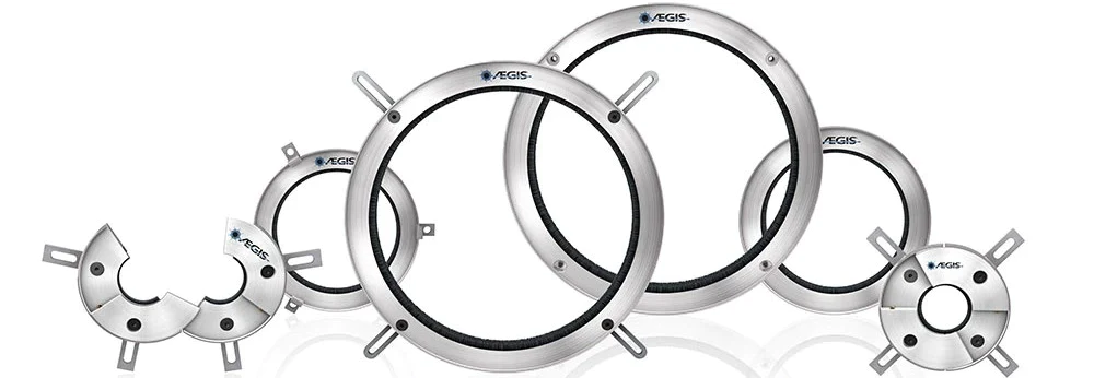
In Part 1 of this series on selecting an AEGIS Shaft Grounding Ring, we discussed solid vs. split ring design, clamp-on, and conductive epoxy mounting. Those rings are all meant to be installed on the outside of an electric motor. This time, we’ll look at mounting options for installing the grounding ring inside the motor.
(suite…)
Shaft Grounding Improves Electric Rail Reliability

Like other electric vehicles, electric trains offer significant benefits over petroleum-powered trains. Electric engines cost around 20% less than diesel engines, and their maintenance costs are 25-35% less. They also produce less noise and far less pollution. Diesel engines produce large amounts of soot, volatile organic compounds, and toxic nitrogen and sulfur oxides. While opinions vary on climate change, most people agree that black grime, acid rain, and smog are things you want less of rather than more.
Like all technologies, though, rail electrification has its challenges. There is the infrastructure problem – electrifying a national rail system is an enormous project, though it can be done. Even with the infrastructure in place, electric trains are still vulnerable to other, sometimes unexpected, problems.
Such as electrical bearing damage. The traction motors in electric trains are controlled by variable frequency drives, which have the unfortunate side effect of generating a voltage between the shaft and frame of the motors they control. This « shaft voltage » can and does discharge through the motor bearings, causing electrical damage and premature failure. Premature failure means premature maintenance, which means more expense for the operator and higher ticket or freight charges for consumers.
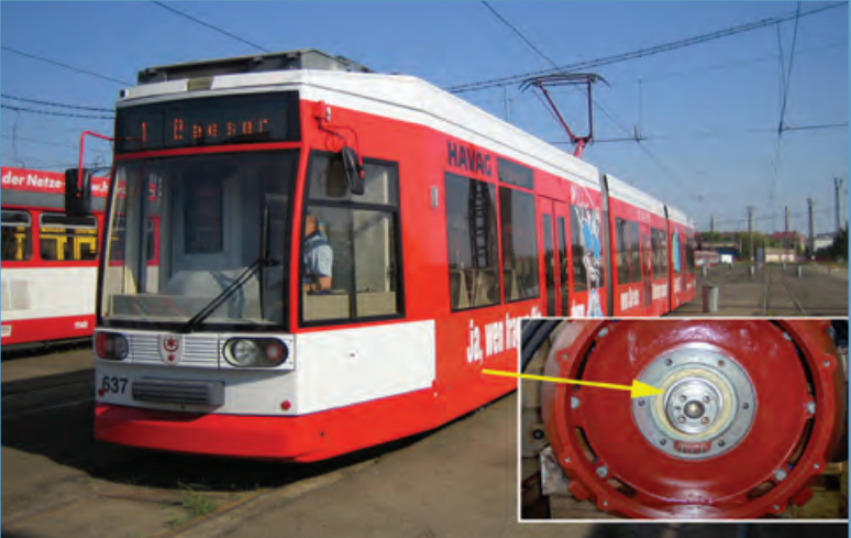
Variable frequency drives can also produce electromagnetic interference (EMI), disrupting controls and other electrical systems on the train.
Luckily, both of these problems are soluble. The AEGIS® Shaft Grounding Ring creates a low-resistance electrical path between the motor shaft and frame. Consequently, shaft voltage bleeds harmlessly through the ring instead of arcing through the bearing. At the same time, it guides electrical noise back to the drive instead of leaving it to wander freely and interfere with other systems.
We’ve done a case study on shaft voltage reduction in electric trains in Halle (Saale), Germany. Before AEGIS was installed, the motors built up 7-8 volts before discharge occurred. Our Shaft Grounding Rings reduced that to under one volt, essentially eliminating discharge through the bearings.
AEGIS Shaft Grounding Rings also have a 2-year extended warranty against bearing fluting damage. No other form of shaft grounding offers a warranty like this.
To learn more about AEGIS shaft grounding and best practices for electrical bearing protection – for motors and generators – sign up for a training. We offer monthly live training webinars, and we can also visit your facility to review your exact application.
How to Choose a Shaft Grounding Ring – Part 1
We are proud to offer AEGIS Shaft Grounding Rings to fit almost any possible inverter-fed motor system. But the downside of flexibility is complexity. We offer grounding rings in five basic mounting styles, with additional options of solid or split rings and different mounting hardware, making for quite a few options. In this series of posts, we will try to demystify the process of choosing a grounding ring for your motor.
Solid and Split Mounting Rings
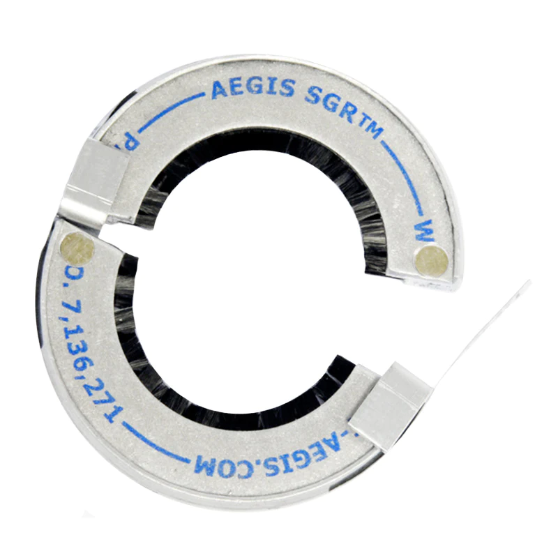
Three of our mounting styles are available in solid and split versions, so let’s start there. Solid rings can only be installed on a motor while it’s out of service. You would use these on a new, yet-to-be-installed motor or a motor that has been disconnected from its load equipment. For in-service motors, you would prefer a split ring. If the motor is already coupled to its equipment, you can open the ring and then close it around the shaft without going through the trouble of disconnecting the motor and load.
Please note that split rings are specially constructed to hold together. We highly recommend against splitting a solid ring in half. A cut ring is likely to fall apart; even if it holds together, its conductive microfibers may fall out.
Clamp-On Mounting Rings
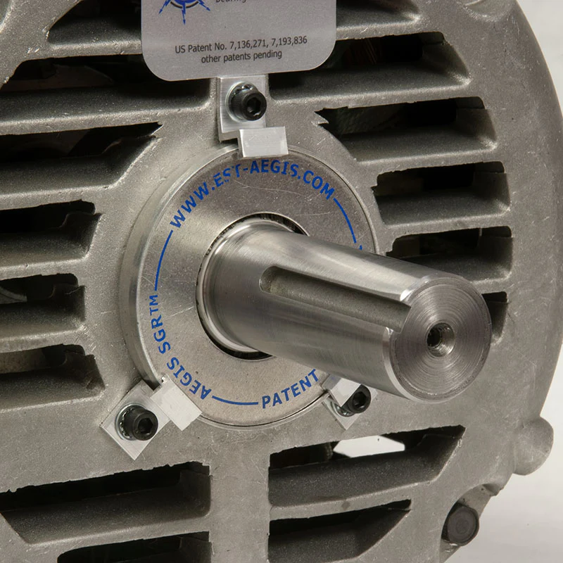
The first mounting style is Clamp-On. These rings come in solid (suffix -1 and -2) and split versions (-1A4 and -2A4), and are held in place by small brackets bolted to the motor face. The only difference between a -1 and a -2 SGR is in the bolts for the bracket. -1/-1A4 come with 6-32 x 1/4 screws (inches), and -2/-2A4 use M3 x .50 x 8 mm screws.
Clamp-On SGRs
Clamp-On SGRs are almost always installed on the outside of the motor. This is a disadvantage in very wet and very dirty environments. And the bolts can’t be screwed directly into the motor, so you need to drill and tap threaded holes for them. But clamp-on rings offer a low profile, so they can usually be mounted on close-coupled equipment, and they are the most economical mounting style.
They are available for shaft diameters from 0.311″ (7.9 mm) to 6.02″ (152.9 mm). Like all SGRs except for uKITs, you must measure the shaft diameter where the ring will sit, and there must be at least 3/8″ (9.5 mm) length of shaft available.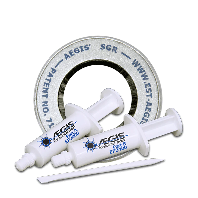
Epoxy-On Rings
Like clamp-on rings, Epoxy-On rings come in solid and split versions, with suffixes -0AW and -0A4W. Their big advantage over clamp-ons is that they don’t require drilling and tapping the motor. Instead, you can just grind off the paint on the motor face where the ring will sit, mix the two-component conductive epoxy, apply it to the motor face, and then apply the ring. These SGRs’ ease of installation, especially the split style, makes them popular with maintenance staff and electrical and HVAC contractors.
AEGIS Shaft Grounding Rings also have a 2-year extended warranty against bearing fluting damage. No other form of shaft grounding offers a warranty like this.
To learn more about AEGIS shaft grounding and best practices for electrical bearing protection – for motors and generators – sign up for a training. We offer monthly live training webinars, and we can also visit your facility to review your exact application.
Improving Reliability in Power Generation with Shaft Grounding
Electric power is fundamental to the modern world. With increasing electrification in areas like transportation and HVAC, reliable electricity production has never been so important. So utility companies and other producers take reliable generation very seriously. The costs to the utility of unplanned downtime can be astronomical.
What is the Weakest Point of a Generator?

The weakest point of any rotating equipment – generator, motor, or whatever – is the bearings, where the rapidly spinning shaft meets the stationary frame. If a bearing fails, the machine fails. So premature bearing failure must be guarded against.
In addition to mechanical damage, bearings are subject to electrical bearing damage from arcing in the bearings. For a generator, this can come from many sources: static buildup on the shaft, asymmetry in the generator’s windings and frame, and stray voltage from the exciter or other sources. Whatever the source, it leads to a voltage across the bearings, which discharges by arcing through them. This degrades the grease and creates roughness in the smooth surfaces of the bearing. The damage accrues over time and can eventually lead to premature failure.
Protection from Electrical Bearing Damage

Most generators (and large motors) come with one insulated bearing, partially protecting against electrical bearing damage. But for full protection, you also need to protect the uninsulated bearing with reliable shaft grounding like the PRO Series AEGIS Shaft Grounding Ring. The grounding ring gives a low-resistance path between the shaft and frame, so electricity travels through the ring instead of arcing through the bearing.
With an insulated bearing and an AEGIS PRO Ring, the generator is well-protected against premature failure from electrical bearing damage. Plant managers can rest a little easier, knowing they have one less thing to worry about.
AEGIS Rings also come with a 2-year extended warranty against bearing fluting damage. No other form of protection against VFD-caused bearing damage offers a warranty like this.
To learn more about AEGIS shaft grounding and best practices for electrical bearing protection – for motors and generators – sign up for a training. We offer monthly live training webinars, and we can also visit your facility to review your exact application.
The Five Most Common Causes of Bearing Failure
Although we talk in this blog mainly about electrical bearing damage, there are plenty of other sources of damage and failure modes for motor bearings. Although there are several guides and schools of thought out there, we’ll focus on one set of five sources of damage. The following is adapted from an article by SKF called 5 Most Common Causes of Bearing Failure in Electric Motors and What to Do About Them.
5 Sources of Bearing Damage in Electric Motors
In no particular order, they are:
Inadequate lubrication and contamination
Bearings spin at high speed, and without adequate lubrication, you will end up with metal-metal contact, causing wear, heating, and possible contamination of the lubricant. The first preventive measure is to check that the regreasing lubricant type, volume, and interval are appropriate. If there is contamination, check the seals. In some cases, a more-viscous lubricant may be needed. (It should be noted that over-greasing can also cause problems.)
Electrical erosion
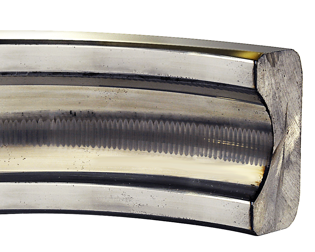
Regular readers of this blog won’t be surprised to see this one on the list. Electric current, typically a side effect of variable frequency drive control, passes through the bearings. The end result is bearing fluting (image at right) and failure. This can be mitigated in several ways. Our preferred method – this being the AEGIS® blog – is to install an AEGIS Shaft Grounding Ring on motors under 100 hp/75 kW and an AEGIS ring and an insulated or hybrid bearing at the opposite end. Other approaches include two insulated bearings and an insulated coupling for the driven equipment or a sinewave filter capable of converting the drive’s current and voltage waveforms to sinewaves. These solutions are effective but more expensive than shaft grounding.
Vibration
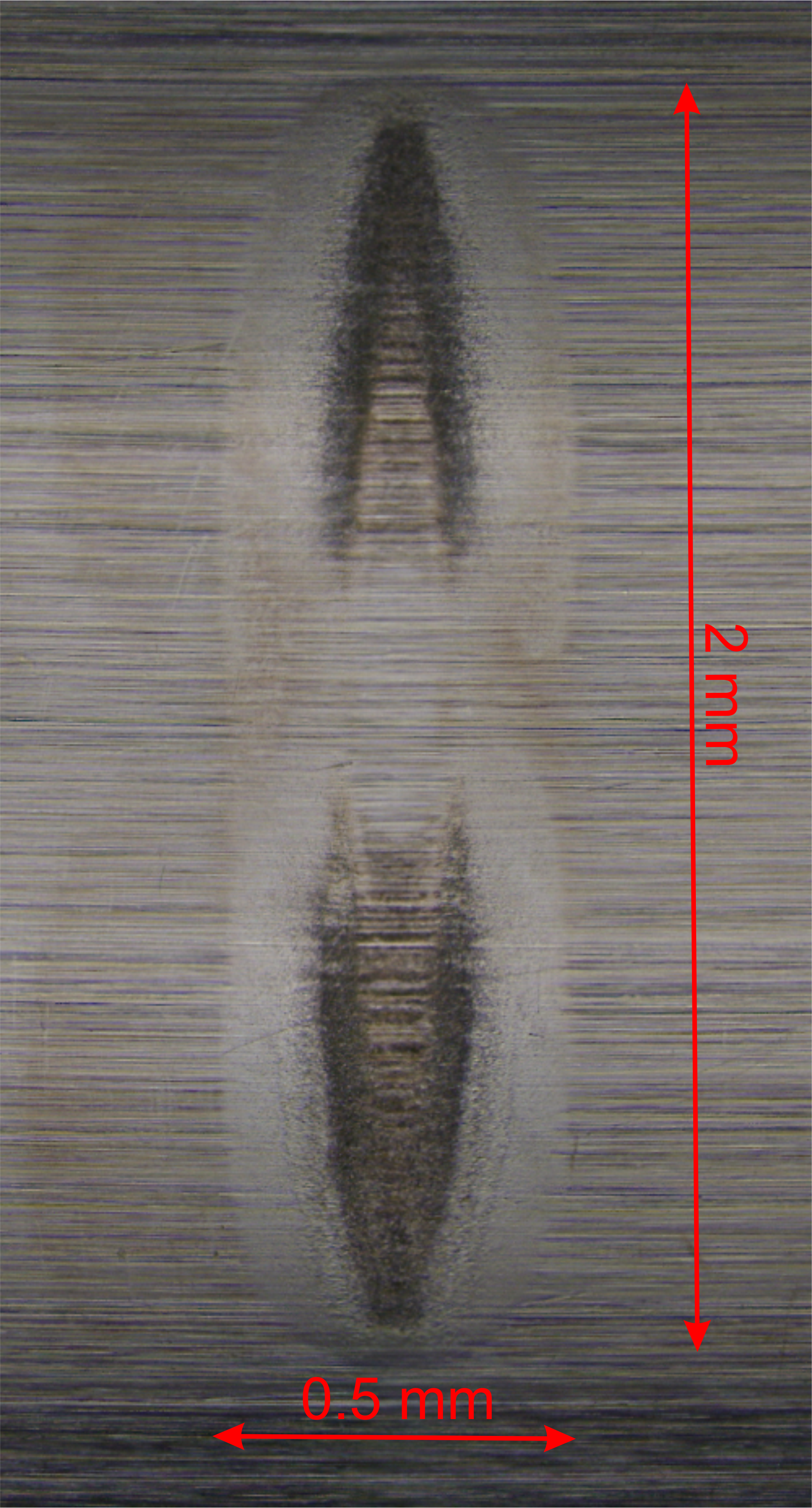
Motor bearings can be damaged by vibration, both during transportation and even while sitting in storage. The vibrations create marks in the bearing races called false brinelling (shown at right; which somewhat resembles fluting). This can be prevented during transport by locking the shaft axially with a flat piece of steel bent into a « U » shape while preloading the non-drive end and then radially locking the drive end with a strap. To prevent vibrational damage during storage, you can turn the shaft periodically so any vibrational contact is spread across the bearing surface (rather than building up into false brinelling).
Improper installation and setup
This can cause several types of damage. Common mistakes include using a hammer to couple the shaft to the load (which can cause true brinelling), misalignment, imbalance, applying excessive belt tension, and errors in mounting, causing overloading. To avoid these errors, always follow the recommended installation procedures and use quality instruments to determine alignment, tension, etc.
Insufficient load
Bearings need a minimum load to function properly. Inadequate load can be as damaging as excessive load. Damage from insufficient load appears as smearing on the rolling elements and races. This is especially important with cylindrical roller bearings since they are designed for larger loads. (This does not apply to preloaded bearings.)
It is worth pointing out that these damage modes are not mutually exclusive and may interact with each other. For instance, insufficient load may make electrical erosion happen faster (by allowing shaft voltage to build up higher before discharge occurs). Electrical erosion also contributes to lubricant contamination because the arcing chemically degrade the grease and releases microscopic metal particles into the lubricant.
Check With Your Bearing Manufacturers
If you’d like to learn more, most major bearing manufacturers – and several bearing distributors – have resources available on common causes, appearance, and prevention of bearing damage.
As for electrical bearing damage, AEGIS Shaft Grounding Rings have a 2-year extended warranty against bearing fluting damage. No other form of shaft grounding offers a warranty like this.
To learn more about AEGIS shaft grounding and best practices for electrical bearing protection, sign up for a training. We offer monthly live training webinars, and we can also visit your facility to review your exact application.
Electrical Bearing Protection Q&A – Part 31 Detecting Damage
Q1. Are there any widely accepted ways to quantify the degree of electrical damage a bearing has sustained?
A1. You would have to do vibration analysis and monitor the spectrum over time, as illustrated to the right. Vibration analysis can also, of course, detect other types of damage. Fluting from electrical bearing damage has a well-known vibrational profile. That is, well-known to vibration analysts; less so to non-specialists. We have seen webinars by the Mobius Institute that talked about fluting and pointed out its characteristics in the vibrational spectrum.
Shaft voltage testing is not good at telling you how much damage has accrued. To some extent, you can infer damage based on peak shaft voltage trends. If peak shaft voltage decreases over time, we interpret that to mean that bits of metal blasted out of the bearing have made the grease more conductive, so discharge occurs at lower shaft voltage. But that is less indicative of the degree of damage than a thorough vibration analysis.
Q2. In your webinars, you say that, as a rule of thumb, damage may occur above five volts of shaft voltage. Is that peak-to-peak voltage?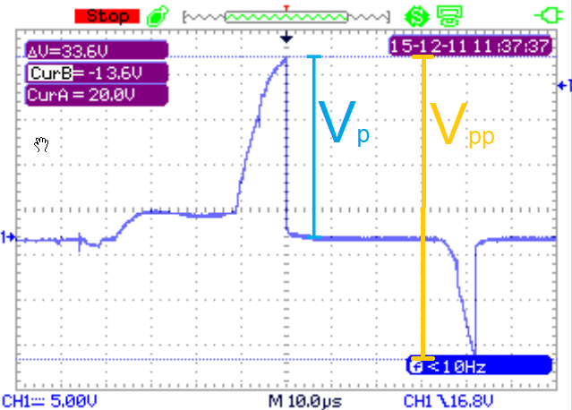
A2. No, that’s 5Vpeak. That would be 10Vpp, which people often prefer because many oscilloscopes report it automatically. Below 5Vp, you may still have occasional discharges through the bearing, but they will not be energetic enough to do serious damage over the natural lifetime of the bearing. Discharges of 5V or less might theoretically cause failure eventually, but in practice, the bearing will fail of « natural causes » before the electrical damage accumulates enough to cause failure on its own.
It’s worth pointing out that the energy released when voltage discharges are proportional to the square of the voltage. If you compare damage from different shaft voltage levels, if the voltage is doubled, the energy in the discharge is quadrupled. So if 10V does one unit of damage, 20V could do four units of damage, and 5V could only do one quarter.
Q3. Does the shaft voltage change with motor speed?
A3. Yes, but not too significantly. The peak shaft voltage will be the same, because it’s determined by the motor’s internal capacitances (which don’t change) and the drive output’s common mode voltage. The common mode voltage won’t change in magnitude (height), because its size is determined by the drive’s bus voltage (which is fixed). But it will change shape with motor speed, and so will the shaft voltage.
Every time an IGBT (switch) in the drive switches on or off, the common mode voltage will step up or down. At different speeds, those IGBTs will spend different amounts of time in the On and Off states, and that will determine the shape (but not the height) of the common mode (and shaft) voltage.
We aren’t aware of any smoking-gun evidence that motor speed makes a big difference to how quickly bearings are electrically damaged. We suspect that lower speeds may be somewhat worse for electrical damage than higher speeds, but we don’t know of any proof, and at any rate, the difference is small.
AEGIS Shaft Grounding Rings also have a 2-year extended warranty against bearing fluting damage. No other form of shaft grounding offers a warranty like this.
To learn more about AEGIS shaft grounding and best practices for electrical bearing protection, sign up for a training. We offer monthly live training webinars, and – pandemic restrictions permitting – we can also visit your facility to review your exact application.
Why Should You Care About the Total Cost of Owning an Electric Motor?
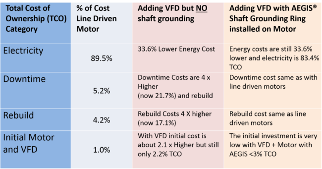
Last month, we discussed Volume 3 of the 2021 MSMA report on potential savings through improved efficiency. Let’s expand on how you can apply the findings of that report. Did you know that the cost of electricity is 90% of the total cost of owning an electric motor for a period of 20 years? The remaining 10% is the cost of the motor itself (1%), downtime (5%), and re-build costs (4%), as estimated by the U.S. Department of Energy.
So here is where variable frequency drives (VFDs) come in: Using a VFD to drive an electric motor can save energy, usually 30-50% or more, especially in applications with varying loads. With VFDs, motors do not need to run at full speed but can be run at the most efficient speed. With a drive, you can save energy and eliminate wasteful mechanical throttling and damping.
For example, even a 20% reduction in fan speed can reduce energy consumption by nearly 50%. In fact, reducing a fan’s speed by half cuts the horsepower needed to run it by a factor of 8! So you can easily see that adding a VFD to a system can save a tremendous amount of energy and, therefore money.
What If There are Other Hidden Costs?
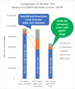 What if the energy efficiency increases, but uptime and reliability suffer? Then the energy savings vanish! Shaft voltage and bearing current induced by VFDs can wreak havoc with motor bearings, dramatically shortening motor life and causing costly repairs, often repeatedly, over the lifetime of the motor. To mitigate these currents and realize the full potential of VFDs, a reliable method of shaft grounding is essential. We will therefore compare three Total Cost of Ownership scenarios:
- Line driven motor (no VFD)
- VFD driven motor with no shaft grounding ring (bearing protection) installed
- VFD driven motor with a shaft grounding ring installed
So here is an example: Let’s say you pay $10,000 for a 200 HP (150kW) motor and operate it for 20 years, with and without a VFD. Your total cost of ownership is as follows:
Line Driven Motor (no VFD)
- Electricity: $855,000
- Downtime from repair (1 x in the 20-year period): $47,500
- Rebuild costs (1 x in 20 years): $38,000 (removal, repair, replacement, alignment, labor)
- Cost of the new motor: $10,000
Total cost of ownership over 20 years: $950,500
Now let’s compare this to a motor with a VFD but no shaft grounding ring
- Electricity: $570,000 (VFD saves 30% in energy costs)
- Downtime costs: $190,000 (4 x motor failure from fluted bearings)
- Rebuild costs: $152,000 (removal, repair, replacement, alignment, labor)
- Cost of Motor + VFD: $20,000
Total cost of ownership over 20 years: $932,000
Last, let’s compare the VFD driven motor with a shaft grounding ring installed.
- Electricity: $570,000 (you still get the savings!)
- Downtime costs: $47,500 (1 x in 20 years – nothing lasts forever!)
- Rebuild costs: $38,000 (1 x in 20 years – you eliminated the frequent bearing failures!)
- Cost of the Motor + VFD + Bearing Protection: $22,000
Total cost of ownership over 20 years: $677,500: You save $273,000 on this 200 HP (150kW) motor
The savings are proportional to the power (hp/kW) rating of the motor, so now ask yourself:
- How many motors do I have in my facility?
- How many are on VFDs?
- How many will be operated by VFDs in the next 10 years?
- Do all my motors have bearing protection (shaft grounding rings) installed?
- Does my motor and drive specification require shaft grounding rings on the motors?
And last but not least: If all of your motors had bearing protection,
- How much money would I save?
- How much more profitable would my operations be?
- Can I really afford NOT to specify motors with shaft grounding rings installed?
Choosing a New Electric Motor
When you purchase new motors, the easiest solution is to select models that already have a shaft grounding ring installed by the manufacturer. There are many options for this from most motor manufacturers, such as Baldor (ABB); U.S. Motors (Nidec); WEG Electric; Marathon; LEESON; TECO-Westinghouse; and GE Industrial Motors (Wolong). For motors already in service, whenever a motor is re-wound or repaired by a motor repair shop, a shaft grounding ring should be installed at the same time.
Whether factory-installed or fit in the field, AEGIS Shaft Grounding Rings also have a 2-year extended warranty against bearing fluting damage. No other form of shaft grounding offers a warranty like this.
To learn more about AEGIS shaft grounding and best practices for electrical bearing protection, sign up for a training. We offer monthly live training webinars, and – pandemic restrictions permitting – we can also visit your facility to review your exact application.
Electrical Bearing Protection Q&A – Part 30 Grounding Rings and Brushes
Q1. What are the pros and cons of using a shaft grounding ring, as opposed to a shaft grounding brush?
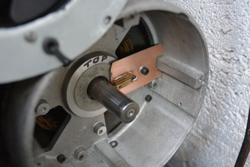
A1. Shaft grounding brushes tend to wear more than AEGIS® rings, but they are very good in some applications. They’re especially good at conducting low frequency and dc current. So they’ve always been used in dc motor commutators. But if you’ve got high-frequency current – such as shaft voltage discharge, high-frequency circulating current, or rotor ground current – an AEGIS ring will work better because it has lower impedance to high frequencies. That’s because high-frequency electricity travels at the surface of conductors, and there’s more surface area on hundreds of thousands of microfibers than there is on a carbon brush.
In some applications, like wind turbine generators, you have high and low-frequency current flowing. For this reason, many manufacturers and wind power companies use carbon brushes and grounding rings in their turbines.
Q2. Are the fibers in a grounding ring also able to cope with dc current?
A2. Yes. It does depend on the amperage – An SGR is good for about 40 amps, and a PRO Ring can take up to 120 A. But that will change with shaft size, too. The bigger the shaft, the bigger the ring. The bigger the ring, the more conductive microfibers. And the more microfibers, the more paths are open for current to travel through, and so the more current can flow. We actually have a new case study about PRO rings discharging static on rolls in a paper mill.
Q3. Does an AEGIS ring offer more or less surface area exposed to the shaft than a carbon brush?
A3. More, sometimes a lot more. You’ve got a band of fibers going 360 degrees around the shaft, as opposed to a few degrees for a carbon brush. A carbon brush may be wider than that band of fibers, but you always end with more surface contact area with an AEGIS ring.
Another factor is that the shaft and brush surfaces have microscopic roughness. When installed, it looks like you’ve got contact all over the brush. But in reality, there’s only a small percentage of the brush’s surface area in actual electrical contact with the shaft. And all the current from the shaft moves through that small fraction of the brush surface. This can cause what’s called hotspotting, where the contact areas end up glazed by overheating from the high current density.
With an AEGIS ring, you’ve got hundreds of thousands, if not millions, of microfibers in electrical contact with the shaft. They’re either in physical contact with it, or they’re close enough to it for non-contact grounding. (For more on non-contact grounding, see this IEEE paper.)
AEGIS Shaft Grounding Rings also have a 2-year extended warranty against bearing fluting damage. No other form of shaft grounding offers a warranty like this.
To learn more about AEGIS shaft grounding and best practices for electrical bearing protection, sign up for a training. We offer monthly live training webinars, and we can also visit your facility to review your exact application.
Takeaways from the 2021 DoE Motor System Market Assessment: Volume 3
In 2016, the U.S. Department of Energy initiated a Motor System Market Assessment (MSMA), led by Lawrence Berkeley National Laboratory, to study the enormous base of electric motors in the U.S. Five years later, they released the first of three volumes of a report summarizing and analyzing the MSMA. Volume 1 summarized key attributes of the motors in use in the industrial and commercial sectors. We talked about Volume 1 back in May and June 2021. Later, Volume 2 assessed the motor and drive supply chain. Finally, in July of 2022, the long-awaited Volume 3 was released, covering potential energy savings from various changes to motor systems.
Changes to Motor Systems That Increase Energy Savings
The report identified three major areas of opportunity:
- Improved load matching: For constant loads, this would be replacing oversized motors with smaller ones. For variable loads, it would mean adopting variable frequency drives (VFDs) to control the motors’ speed/torque. As mentioned in Part 1 of the report, only 16% of industrial motor systems, and 4% of commercial, currently use drives.
- Motor upgrades: Many motors in current use could be replaced by newer, more energy-efficient models.
- Improving the condition of fluid distribution systems: Repair and efficiency upgrades to air, water, coolant, and other fluid distribution systems.
The report also explored a fourth category, emerging or advanced technologies, like permanent magnet and switched reluctance motor topologies.
Improved Load Matching for Industrial and Commercial Systems
In this blog post, we will be mainly interested in the improved load matching category, which offers the largest savings for both industrial and commercial systems, as shown below. Out of the 547 TWh (1 TW = 1000 GW) used annually by industrial motor systems, it is estimated that 45 TWh (8.2%, worth $3.2 billion) could be saved by better load matching. For commercial systems, 69 TWh (worth $9.4 billion) could be saved, 13% of the total 532 TWh used per year. (Click the images to enlarge.)

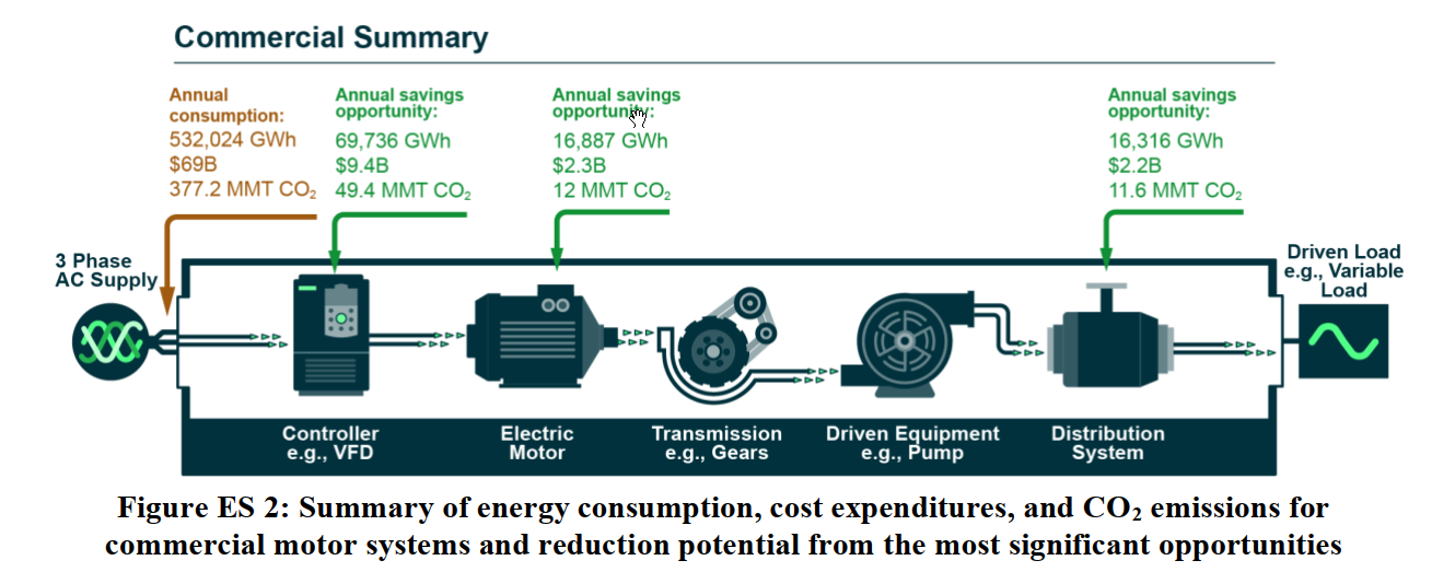
As shown, lesser amounts could be saved by motor upgrades and fluid distribution systems. The former makes the bigger difference in the commercial sphere; the latter in industrial. In this post, we will focus on load matching, the largest source of savings in both use categories.
Limitations
Before going on, it is appropriate to mention some limitations of this research. Firstly, it neglected motors under 1 hp, which make a doubly small contribution to total energy use because of both their small consumption and small population. Secondly, it did not consider interactions between the savings opportunities. For instance, premium efficiency motors have lower slip, and the higher resulting speeds may exacerbate other inefficiencies. (Incidentally, this can be compensated for when the motor is on a drive – another interaction!)
For another example, suppose a motor driving a variable load was put under VFD control. If the motor was not suitable for inverter control, it could be subject to winding and bearing damage and premature failure, introducing additional cost (of repair or replacement) and possibly unplanned downtime, cutting into the monetary savings. If, on the other hand, when the drive was introduced, the motor was replaced with a high-efficiency inverter-ready motor (with shaft grounding, of course), the larger upfront investment would reliably pay off in savings from load matching and motor efficiency upgrade.
Looking at the Cost-Effectiveness of the Proposed Changes
The idea of an upgrade to one part of the system causes failure in another leads to our final point: Just how cost-effective are the changes proposed? To assess this, the report’s authors compared the calculated payback period in years (cost of installation divided by the change in annual operating costs before and after installation) and compared it to the respondent facilities’ maximum acceptable payback period. The following graph shows the cost-effectiveness of adopting VFD control for variable load systems.
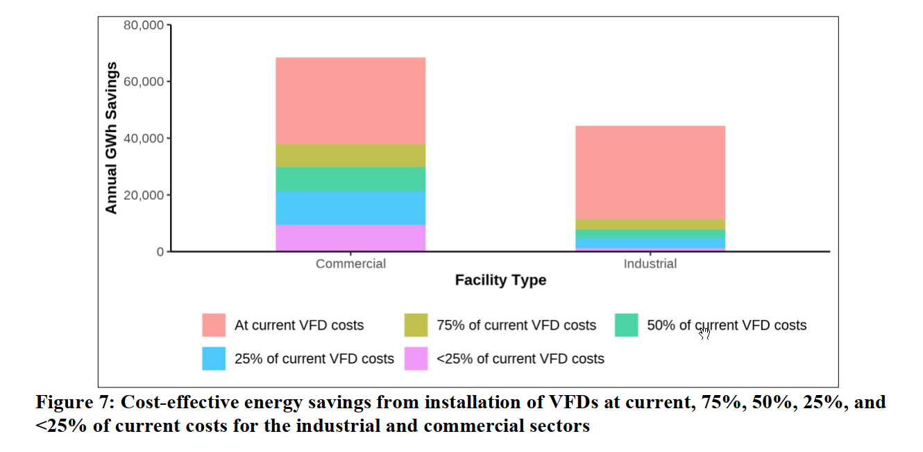 At current prices, VFD control is cost-effective for 45% of eligible commercial systems, and for 74% of eligible industrial systems. (Salmon bars – the other bars show what would be considered cost-effective if the price of drives decreased.) It is interesting that the percentage of cost-effective savings is so much lower for commercial applications. Part of the difference is that industrial motors are larger on average, and drives have a lower $/hp cost at higher power (e.g., one 20 hp drive costs less than two 10 hp drives). The bottom line is, at 2021 prices, both industrial and commercial systems could save over 30 GWh per year. At average prices of $0.086 (industrial) and $0.13 /kWh (commercial), that means savings of $2.8 and $4.0 billion. If concerned companies adopted longer acceptable payback times, even more staggering savings would be possible, simply from adopting drive control for variable load systems.
Of course, energy savings are energy savings, but monetary savings can be wiped out by downtime and repair costs. So facility managers would be well advised to ensure that motors put under drive control are resistant to destructive side effects of VFDs. That is, inverter duty motors with robust winding insulation to resist damage from high dV/dt, and reliable shaft grounding like AEGIS® rings to prevent electrical bearing damage.
This blog post has barely scratched the surface of Volume 3 of LBNL’s report on the MSMA. If you are interested, we urge you to give it a read. You might find ideas that can help your own facility save money, or find potential pitfalls in a plan you’re currently working on.
AEGIS Shaft Grounding Rings have a 2-year extended warranty against bearing fluting damage. No other form of shaft grounding offers a warranty like this.
To learn more about AEGIS shaft grounding and best practices for electrical bearing protection, sign up for a training. We offer monthly live training webinars, and – pandemic restrictions permitting – we can also visit your facility to review your exact application.