

Author: AEGIS
Questions and Answers from the CSE Motors and Drives Webcast
On February 22, 2018, CSE Magazine hosted a webinar called “Critical Power: Motors, Variable Frequency Drives (VFDs), and Variable Speed Drives”. Some of the attendees brought up some good questions relating to specifying shaft grounding rings and bearing damage that we’d like to address here:
1. Can VFDs damage motors? If so, how?
Yes, the pulsed nature of VFD output voltage can damage motors in multiple ways. Firstly, high peak voltages and fast rise times can burn out the insulation in non-inverter duty motors. Inverter duty motors mitigate this damage by using Class F or H insulation in their motor windings.
But VFDs also damage motor bearings (by mechanisms described below), and most so-called inverter duty motors do not yet include protection against VFD-caused electrical bearing damage. To avoid premature bearing failure, it would be prudent for a specifying engineer to require that VFD-fed motors be equipped with factory-installed shaft grounding rings.
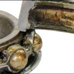
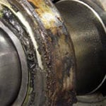
Specifying suitable motors is the key, and all of the following motor manufacturers have motors with shaft grounding rings factory-installed:
- Baldor
- WEG Electric
- Regal Beloit (Marathon, LEESON)
- TECO Westinghouse
- GE
An actual example of a specification follows:
SECTION 23 05 13 – ELECTRICAL PROVISIONS FOR HVAC EQUIPMENT
1.3 B. Electrical bearing damage protection: Submit product data and installation instructions for each of the following conditions:
1. New fan and motors.
2. Retrofitted fan and pump motors.
3. Shaft voltage tester.
2.1 MOTORS
Inverter Duty Motors: Where fan or pump motors are used in conjunction with, or controlled by, a variable frequency drive (VFD), motors shall be premium efficiency, suitable for VFD operation, in accordance with NEMA MG.1 (This paragraph could also include the phrase “…with Inverter rated winding insulation and shaft grounding rings installed by the motor manufacturer)
2.2 ELECTRICAL BEARING DAMAGE PROTECTION
A. Shaft Grounding Rings
- All motors operated on variable frequency drives shall be equipped with a maintenance free, conductive microfiber, shaft grounding ring with a minimum of two (2) rows of circumferential microfibers to discharge electrical shaft currents within the motor and/or its bearings.
- Motors up to 100 HP shall be provided with a minimum of one (1) shaft grounding ring installed either on the drive end or non-drive end.
- Motors over 100 HP shall be provided with an insulated bearing on the non-drive end and a shaft grounding ring on the drive end of the motor.
- Grounding rings shall be installed in accordance with the manufacturer’s recommendations.
- Existing Motor Retrofit:
- Grounding Ring Kits shall be equivalent to Aegis SGR uKIT, solid ring only. Grounding Rings shall be suitable for Drill and Tap installation or Conductive Epoxy installation.
- Drill and Tap: Avoid using Loctite or other non-conductive material to secure the screws.
- Conductive Epoxy: Remove paint from motor surface, apply epoxy and hold bracket in place until firm. Allow epoxy to cure for 4 hours at 75F, or use a heat gun continually for 10 minutes, then allow to cool.
- Colloidal Silver Shaft Coating: The silver coating enhances the conductivity of the shaft and also lessens the amount of corrosion that can impede the grounding path. Apply to the shaft where the grounding ring microfibers are to be installed. Use a heat gun to cure. Apply a second coat, and re-cure.
B. High-Frequency Ground Strap
- Provide grounding straps as manufactured by AEGIS, or equivalent to ensure a very low impendence path to ground from the frame of the motor for high frequency currents generated by VFDs.
- Grounding straps shall be constructed of flat braided tinned copper with tinned hole at one end and ring terminal at the other. All motors operated on variable frequency drives shall be bonded from the motor foot to system ground with a high frequency ground strap made of flat braided, tinned copper with termination to accommodate motor foot and system ground connection.
- Continuity Testing: After installation, test for conductive path to ground using Ohm meter. One probe on metal frame of SGR and one probe on bare metal of motor frame. NOTE: motor must be grounded to common earth ground according to applicable standards.
C. Shaft Voltage Testing
- Measuring the shaft voltage on VFD driven motors provides the valuable information to determine if there is a potential risk of bearing damage from electrical bearing discharges.
- Shaft voltage readings and waveforms shall be used to validate motor performance.
- Provide shaft voltage testing kit equivalent to Aegis Model OSC-9100MB-W2, complete with the following:
- Two 1x / 10x probes, one shaft voltage probe with SVP tip
- 1000V CAT III multimeter test leads
- Instant image capture feature
- USB flash drive for waveform recording
- 5-hour rechargeable Lithium Ion battery
- Carrying case.
PART 3 – EXECUTION
3.2 BEARING PROTECTION TESTING
- Bearing protection shall be tested for each VFD driven motor, in accordance with manufacturer’s recommendations.
- Shaft voltage testing shall be performed by a factory-trained and authorized Aegis technician. Technician shall train the owner’s personnel and demonstrate the proper use of the testing equipment.
- Record test results and incorporate into project closeout documentation.

2. What about common mode ground current, bearing fluting?
There is more than one source of bearing currents in VFD-fed motors, any one of which can lead to fearing fluting damage and failure. There are many technical papers published on this subject, for example “A Practical Guide to Understanding Bearing Damage Related To PWM Drives” by Don MacDonald and Will Gray, and ABB Drives’ Technical guide No. 5: Bearing currents in modern AC drive systems
The two most common sources of bearing currents are capacitively induced EDM Currents and high frequency circulating currents, which are addressed in detail in the AEGIS Bearing Protection Handbook.
- Capacitively induced currents are from the common mode voltage
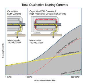 supplied from the drive to the motor – positive and negative pulses – which are then capacitively coupled/electrostatically induced onto the motor’s shaft, and which then may discharge in the motor’s bearings. These capacitive EDM currents are present in ALL VFD driven motors and require a path to ground away from the motor’s bearings – such as is provided by the shaft grounding rings described in question 1 above.
- High frequency circulating currents are present in motors over 100 HP (75 kW) and result from electromagnetic induction. They are induced along the shaft by the magnetic field from the common mode current in the stator windings. These currents circulate from frame to shaft and back, through the motor bearings.
3. What is AEGIS’ role in motors & drives?
AEGIS shaft grounding rings are specifically designed to provide the most reliable path to ground for capacitive induced bearing currents. The AEGIS ring’s unique design features hundreds of thousands to millions of specially engineered conductive microfibers that encircle the motor shaft. With so many electrical transfer points the ring provides continuous electrical contact.
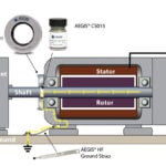
Motor under 100 HP only needs a shaft grounding ring to protect the bearings.
Designed with specific mechanical and electrical characteristics that minimize wear and maintain conductivity, AEGIS microfibers will last for at least the L10 life of the bearing. Based on wear of less than 0.001” [0.025mm] during 10,000 hours of testing, they are expected to withstand over 200,000 hours of continuous operation.

Motors over 100 HP require shaft grounding ring on the DE and insulation on the NDE
Through our patented design, AEGIS conductive microfibers are a wear-to-fit design which ensures that the fibers don’t “wear out” during the bearing’s life They exhibit minimal wear with the ability to flex without breaking. During the life of the ring the minimal wear characteristics ensure that the fibers only wear to the exact diameter of the motor’s shaft and no further, maintaining the nanogap contact which allows the AEGIS ring to continue to operate effectively and protect the motor’s bearings. In testing, the fibers were proven to withstand 2 million direction reversals (to 1800 RPM) with no fiber fatigue or breakage.
However, shaft grounding rings cannot prevent damage from high frequency circulating currents in larger motors. In motors over 100 HP (75 kW), one bearing must be insulated, with a shaft grounding ring at the other end. Insulating just one bearing interrupts circulating currents and prevents their flow, while the AEGIS ring discharges capacitive shaft voltage (which is still present in larger motors).
4. What about shaft grounding rings for motors in classified areas, and UL listing for motors in non-classified areas
- Hazardous areas: External shaft grounding is not allowed for hazardous environments (Class 1 Division 1, Division 2 or Class 1 Zone 1, Zone 2). However, AEGIS shaft grounding rings may be installed inside an Explosion Proof enclosure per IEEE Std 303™-2004 or inside an XP motor. Marathon Motors manufactures XP motors with AEGIS factory-installed.
- CE and UL requirements: AEGIS® Rings are classified as a “component” and as such are not subject to the requirements of any Directive. The application of CE or UL Mark is not applicable to this component.
5. dV/dt and the need for load reactors with inverter-duty VFDs
Variable frequency drives’ output comprises a series of voltage pulses with extremely rapid off-on transitions. dV/dt is just the rate of change in voltage at during a transition, and is the change in voltage divided by the rise time of the pulse. Typical values are dV = 460 volts and a 20 ns rise time, giving dV/dt = 23,000 volts per microsecond! These transitions are also often measured by their frequency, defined as the reciprocal of the rise time. 20 ns corresponds to a 50 MHz frequency.
With that background, the question of when to use a dV/dt filter must be evaluated. Generally, if there is an impedance mismatch between the VFD and the motor, reflected waves can “amplify” the dv/dt transition which could result in a “overshoot” of voltage which may be 2 or more times higher than the supply voltage. This means that there may be a transition that spikes up to 1000 volts or more on the leading or trailing edge of the pulse. Even inverter-duty winding insulation may break down under voltage spikes like this. In these cases adding a dV/dt filter will help to filter this voltage spike.
 H
 owever, it should be noted that in the motor’s stator windings the pulses will still cause capacitively induced shaft voltage and therefore even with the dV/dt filter bearing discharges would still take place so shaft grounding rings are still needed to provide a path to ground for shaft voltages.
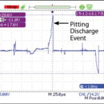
One can measure the shaft voltage with an oscilloscope such as the AEGIS Shaft Voltage tester which would display the presence of shaft voltage and bearing discharges should no shaft grounding ring be installed on the motor.

Case Study: Making Motors Last at Time & Life Building in NYC
Testing VFD driven motors for shaft voltage identifies potential bearing damage risk and avoids down time.
Innovative companies like AKF Analysis & Testing are on the leading edge of technology services to assist building owners in ensuring their mechanical and VFD driven motor systems stay up and running. They deploy highly skilled and experienced vibration analysts and testing specialists from the best in the industry with members from Local 638 and Local 94 and focus on building operations such as chiller plants, air handlers, pumps, and critical system units.
In the case study which follows you will see how shaft grounding rings were successfully implemented to improve reliability for a New York City landmark building:
Making Motors Last at Time & Life Building in new York City
Background on the case study below: In 2007, Tom O’Connell Jr., a partner in AKFA&T, read about the AEGIS SGR Bearing Protection Ring in a magazine and began the process that could eventually end the bearing damage problem at the Time & Life Building once and for all. He called the ring’s manufacturer, Electro Static Technology, and spoke with Adam Willwerth, the company’s sales and marketing manager. Soon after, the two met face to face, and O’Connell decided to recommend the installation of a single SGR shaft grounding ring on the most problematic of all the HVAC motors at Time & Life. Ron Perez, the building’s manager of engineering, consented to the experiment, and follow-up testing showed the ring to be so successful at diverting harmful shaft currents that O’Connell decided to make his company a distributor for the ring.
The full case study is available to read or download: Click here to view. We have also re-published it in this blog.
Making HVAC fan motors last was the goal for tenants of the Time & Life Building, in New York’s Rockefeller Center: Shaft grounding rings were installed to prevent an on-going bearing failure problem with remarkable success. Installed in 2008, these motors are still running today!

Time and Life Building, New York City
A preventive maintenance plan that reduces the total life-cycle cost of operations in a prominent building at the heart of New York City serves as a good example of how the push for greater reliability and up-time in building management has led to finding a solution to a chronic, widespread problem with HVAC motors – electrical bearing damage.
The problem is all too common in AC motors controlled by variable frequency drives (VFDs), which are also known as inverters, adjustable speed drives, etc. These drives are widely used because they can save energy, especially in applications with varying loads. Because many centrifugal fans and pumps run continuously, their motors will use less power if the input is modulated by VFDs. For example, a 20% reduction in fan speed can reduce energy consumption by nearly 50%. With rising energy costs, the use of throttling mechanisms to restrict the work of a motor running at full speed would be wasteful.
However, efficiency alone is not enough if equipment keeps breaking down. That is what was happening at the 48-story Time & Life Building, one of 19 buildings in the Manhattan business and entertainment complex built and partially owned by the Rockefeller Group and known as Rockefeller Center.
More than 100 VFDs control the speeds of the 240 motors that run the building’s HVAC fans and pumps. Unfortunately, a large portion of the savings from these systems has been wiped out by maintenance costs because, in addition to their intended function, VFDs induce powerful, unwanted currents which cause electrical bearing discharges and, ultimately, premature motor failure.
SHAFT GROUNDING
Proper tuning of a drive’s frequency output range and proper grounding of a VFD-controlled motor’s frame are paramount. Only recently has it become clear that without an effective shaft-grounding device as well, stray currents can wreak havoc with bearings, causing premature motor failure. Ironically, some products designed to protect bearings, such as conventional
metal grounding brushes, require extensive maintenance themselves. Others, such as insulation, can shift damage to connected equipment.
 One of the newest and most promising bearing-damage mitigation devices uses patented shaft grounding ring technology to safely bleed off these damaging currents to ground. Engineered with special conductive microfibers, the AEGIS shaft grounding ring safely discharges VFD-induced shaft voltages by providing a very low impedance path from shaft to frame, bypassing the motor’s bearings entirely.
For more than 20 years, since the installation of the first modern VFDs, the Time & Life Building’s maintenance department has dealt with chronic motor and bearing failure. At times, the bearing damage had advanced to the noisy stage, at which an unpleasant, high-pitched sound was transmitted through duct-work. Thanks to the efforts of AKF Analysis & Testing, an engineering firm hired by the Rockefeller Group Development Corp. to periodically test and tune (with harmonic filters) the building’s VFDs, the rate of motor/bearing replacements has dropped from 90 to 20 per year, but in today’s economy that is still too costly. Other attempts to mitigate the problem, including the installation of ceramic bearings on some motors, have produced mixed results, usually proving too costly for the meager improvements gained.
THE SOLUTION AT LAST
Late in 2007 AKF Analysis and Testing read about the AEGIS shaft grounding ring and began the process that could eventually end the bearing damage problem at the Time & Life Building once and for all. AKF A&T decided to recommend the installation of a single shaft grounding ring on the most problematic of all the HVAC motors at Time & Life. Ron Perez, the building’s manager of engineering, consented to the experiment, and follow-up testing showed the ring to be so successful at diverting harmful shaft currents that O’Connell decided to make his company a distributor for the ring.

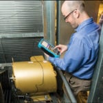
Fan motor in the Time & Life Building with AEGIS Ring installed by AKF Analysis and Testing
It was an unprecedented move. AKF A&T specializes in vibration monitoring and analysis, acceptance testing, critical speed testing, and motor current waveform analysis for preventive maintenance and energy management on behalf of government agencies and businesses in a multitude of East Coast buildings, including hotels, hospitals, laboratories, and office buildings.
Never before had the company endorsed a particular product. The whole phenomenon of electrical bearing damage is so misunderstood that some maintenance managers have lost their jobs over it because replacing a fan motor is a big expense. In an office tower, a motor can be running critical equipment
that supplies air to 30 floors where the tenants are paying as much as $110 a square foot. They have the right to expect the temperature and quality of their air to remain constant. AKF A&T was so convinced of the ring’s effectiveness that they recommended it be eventually installed on all HVAC motors in the Time & Life Building and in other buildings for which they have contracts.
Because AKF Analysis and Testing usually visit a client’s building three or four times a year to run diagnostic tests on the HVAC equipment and tune the VFDs, they have seen the progression of motor bearing damage. Now, the typical procedure is to recommend installation of an AEGIS shaft grounding ring whenever a replacement motor is installed or a motor’s bearings are replaced to ensure that harmful bearing currents have been eliminated and the VFD is running at its optimal performance.
THE EXPERIMENT
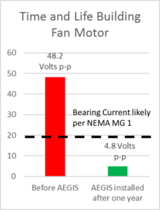
Shaft Voltage readings before and after one year
On February 6, 2008, before the ring was installed on the problematic motor, AKF A&T used a shaft voltage probe and an oscilloscope to measure the discharges from the motor’s shaft at 59.2V (peak-to peak) and 37.2V (peak-to-peak), at two different oscilloscope settings (10μsec/ div and 2μsec/div, respectively), for an average of 48.2V (peak-to-peak). The oscilloscope screen showed rapid dv/dt voltage collapse at the trailing edge of the waveform – typical of the electrical discharges that damage bearings. On February 20, 2008, two weeks after the ring was installed, AKFA&T took a ground-reference reading, for baseline comparison, of 9.21V (peak to-peak) with the oscilloscope set at 40ns/div. Minutes later, AKF A&T took two more shaft-current readings at the same setting: 8.86V (peak-to-peak) and 11.2V (peak-to-peak). A little more than a year later, on March 9, 2009, the motor was checked again by AKFA&T technicians. This time the shaft voltage was even lower: 4.8V (peak-to-peak). The readings may speak for themselves and the Building engineering manager Perez agrees the ring “seems to have resolved the issue.” Based on the positive results, he has installed AEGIS shaft grounding rings on additional fan motors in the Time & Life Building.
What Is the Effect of PWM Drives on Electric Motor Bearings?
Pulse Width Modulated (PWM) power sources, also known as variable frequency drives (VFD), adjustable speedy drives (ASD), “inverters,” or “drives,” cause bearing current problems within electric motor bearings. The most common types of bearing current are capacitively induced shaft voltage discharge, or EDM current, and in larger motors, electromagnetically induced high frequency circulating currents.
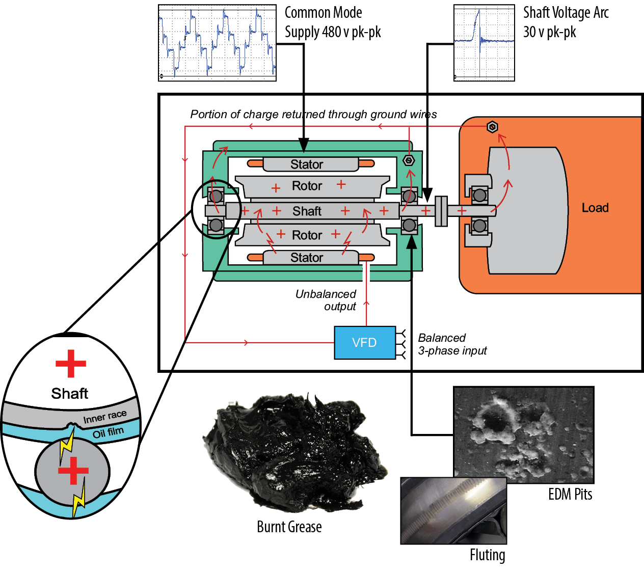
The impedance of the bearing to high frequency discharges is a function of the oil film between the rolling element and the bearing race, load and system design variables, the type of bearing, speed of rotation, and other factors. The bottom line is that as the shaft rotates an oil film forms between the rolling elements and the bearing race. This oil film is dielectric and would not normally not allow current to flow. However, because it is very thin, only 5 to 10 microns thick, when the induced shaft voltage is high enough, [10 to 40 volts peak per NEMA MG1 31.4.4.3] the oil film will break down and allow an arc to pit the motor’s bearing.
Bearing current is the current that arcs through the electric motor bearings and leads to mechanical damage. This damage is evident from the pits in the bearing. While the electric motor is in operation, arcing occurs thousands of times per second. In addition to pitting the bearing, arcing also oxidizes the lubrication, which further decreases the bearing life.
Two potential mechanisms for bearing damage when operating on pulse width modulated variable frequency drives are dv/dt (the change in voltage divided by the change in time), which contributes to EDM currents caused by the parasitic capacitive coupling from stator to rotor, and in larger motors (over 100 HP / 75 kW), the high frequency circulating currents are caused by high common mode current levels.
Discovering and Preventing Bearing Current Damage
 Electric motors are prone to many sources of damage, some more common and some better known. An increasingly common, but still not too well known, problem facing these motors is bearing current. Bearing currents damage the ball bearings with electrical discharge machining (EDM), resulting in motor failure. In addition to the repair or replacement costs of the electric motor, there is the possible loss of production caused by that motor failure. Adding it all together results in one expensive failure!
Bearing currents have been a thorn in the side of motor users for years. However, incidents are rising simply because more people are using pulse-width modulated variable frequency drives (VFDs). We will look at what bearing currents do and how to avoid them.
Bearing Currents Cause Problems
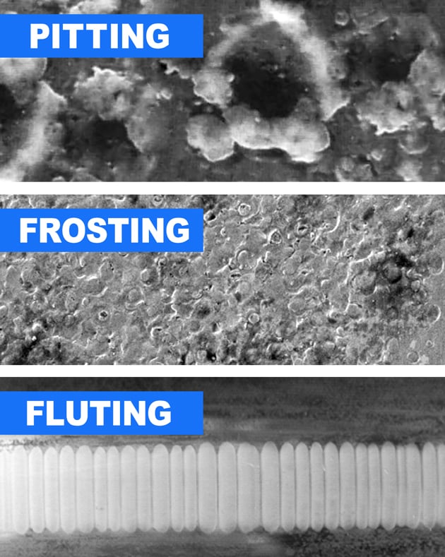
Shaft voltages damage electrical bearings when they discharge in a tiny but destructive electrical arc through the bearings. Pitting, frosting, and fluting are some of the damages caused by that current. These types of damages lead to premature bearing failure, leading to the motor failing as well. In addition, if a conductive coupling is connected to the motor drive end shaft, shaft voltage can discharge through the coupled equipment, damaging its bearing with electrical arcing.
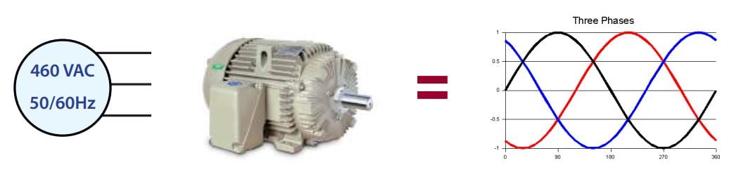
Balanced 3-phase sine wave line voltage

Unbalanced PWM pulses: Common Mode Voltage
Three-phase power is what operates most AC motors. On line power, the three phases always sum to zero volts. The sum of the three phases is also called common mode voltage. The common mode voltage is zero on line power because each phase is a smooth sine wave voltage 120 degrees out of phase with the other two phases. But when a VFD is in control, each phase consists of a series of positive, zero, and negative voltage pulses. The three phases don’t usually sum to zero, so the common mode voltage continuously changes with the pulses driving the motor. This nonzero common mode voltage creates shaft voltage by parasitic capacitive coupling between the stator and rotor.
And when voltage is induced onto the motor’s shaft, that voltage “looks for” a least-resistance path to the ground. Usually, the path of least resistance leads through the motor’s bearings. As described above, shaft voltage discharging through the bearing causes damage to EDM and cumulative electrical bearing.
Why Test Motors for Shaft Voltage?
If your facility relies on electric motors, include testing for shaft voltage in your preventative maintenance (PM) program. These tests are performed on-site, and you receive an analysis of any potential problems.
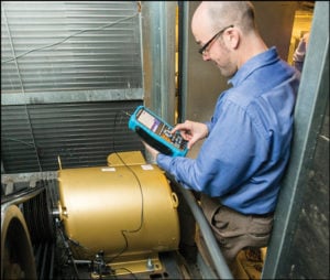 The idea behind an effective PM program is obvious: to stop issues before they become problems. Using an effective testing method for shaft voltage leads to lower cost options than repairing or replacing an expensive motor. Reducing the risk of shaft voltage reduces the risk of bearing failure and presents an opportunity to save substantial expenses.
Testing for shaft voltage is a relatively simple process. A conductive microfiber probe tip safely touches the motor’s spinning shaft and captures shaft voltage data for analysis at an exposed area of the motor’s shaft. The AEGIS Best Practices Handbook explains the step-by-step procedure and many other important topics to protect your motor bearings!
To learn more about AEGIS shaft grounding and best practices for electrical bearing protection, sign up for a training. We offer monthly live training webinars, and we can also visit your facility to review your exact application.
Marathon Explosion-Proof Motors Available with AEGIS Rings Factory-Installed
Marathon Electric offers the industry-leading line of Hazardous Duty™ Division 1 Explosion Proof, NEMA Premium® XRI®, Class I and II, Groups C, D, F & G motors. Marathon’s unique design, combined with AEGIS® Shaft Grounding Ring technology and Marathon’s work with Underwriters Laboratory (UL), minimizes the risk of bearing damage. Marathon’s “BCP” System, featuring the AEGIS Ring, meets all UL requirements while protecting the motor bearings.
With the growing emphasis on energy savings, process engineers, as well as plant maintenance personnel, have turned to variable frequency drives (VFDs) to improve process reliability, uptime, and safety (particularly in hazardous locations) for critical applications. Using VFDs also reduces the energy consumption of the electric motors in their facilities.
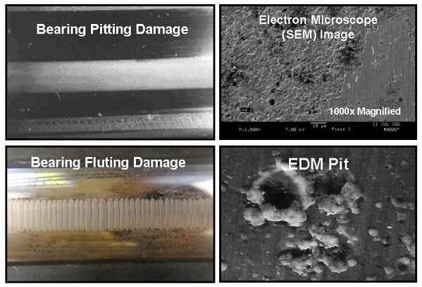 It is well documented that the common mode voltage of VFD output can contribute to motor bearing failure due to electrical fluting (see figure). Unfortunately, unexpected bearing failure can offset much of the savings initially anticipated by the use of VFDs. Effective shaft grounding helps prevent the destructive effects of common mode voltage in these critical applications, facilitating maximum energy savings and reliability.
The option of the AEGIS shaft grounding rings factory installed in these motors is available across the entire product line and comes in stock through 50 HP. The Marathon XRI Explosion Proof Severe Duty motor with “BCP” provides maximum energy savings potential when used with VFD’s, enhanced reliability and uptime, and the “peace of mind” end users demand from their motor/drive systems. Marathon is the only supplier of Division 1, Class I and II Explosion Proof motors with factory-installed AEGIS long-term bearing current protection from VFD-sourced damage!
The Marathon XRI Severe Duty Explosion Proof motor is UL Listed and CSA Certified for use in virtually any hazardous process application. The product features cast iron construction, epoxy interior and exterior paint, Max Guard insulation system, precision balance, thermostats and a generous 3-year warranty.
For more applications information on how you can protect your motors from electrical bearing damage download the AEGIS Best Practices Handbook.
What to Look for When Inspecting Failed Bearings
Electric motors make the industrial world go around. They are found in virtually all manufacturing facilities and are responsible for 64% of all industrial electric power used in the United States.
Why Motors Fail
Your electric motors represent a significant expense. When one fails, the costs associated with that motor add up. Those costs include the price for repair or replacement of the failed motor and the cost of lost production time or unplanned downtime. The cost due to lost production usually dwarfs the motor repair and replacement cost.
As vital as it is to get your motor back up and running, it is as important to find out why it failed in the first place. Discovering the cause of the failure allows you to prevent that problem from causing any future failures. Whether the investigation is done by your maintenance team or by a motor repair, maintenance, or other contractor, it is essential to learn from failures to improve your operations’ reliability.

Bearing failure accounts for over half of all electric motor breakdowns. So, when you look into why the motor failed, start by looking at the bearings.
Inspecting the Bearings
When the motor arrives for repair, cut and inspect every bearing, especially if a VFD controlled it. Inspecting the bearings provides vital information that indicates the best options for repair. Knowing why the bearing failed and taking steps that prevent it from happening again improves the machine’s lifetime performance.
Bearing inspection is also required by AR100-2015, the recommended motor repair practices of EASA (the Electrical Apparatus Service Association). Section 2.2 on Bearings begins, “Bearings should be inspected for failure modes such as spalling, contamination, fretting, fluting, frosting, and scoring or other damage.”
We recommend the following procedure to inspect the bearings for signs of electrical damage due to VFD control. These steps are available in the AEGIS® Handbook. Of course, bearings have many possible failure modes, each of which should also be checked for.
Please Note: Follow established safety precautions and use personal protective equipment, including eye protection, hearing protection, face shield, gloves, and protective clothing.
1. Inspect the outside and the inside of both bearings. Keep a sample of the lubricant to analyze. When examining the lubricant, look for:
- Contamination
- Signs of excessive heat
- Hardening of grease
- Abnormal coloration (blackened grease)
- Excess grease and oil escaping the bearing
2. Remove seals or shields first, then cut the outer race into halves.
3. Inspect the grease and look for any contamination in the bearing.
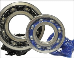
- Burnt Grease: Electrical arcing in the motor bearings causes chemical degradation which deteriorates the lubricating capability of the grease.
- Contamination: Besides burning the grease, arcing knocks small metal particles loose from the bearing races or balls. These loose particles become distributed in the grease. These particles are abrasive and cause the bearing to wear prematurely. Burnt bearing grease is blackened and is oftentimes contaminated with metal particles.
New bearing grease is available in many colors. The blue grease is Polyrex EM, commonly found in electric motor bearings.
4. Clean the bearing’s components using a degreaser or solvent.
5. Inspect for evidence of Electrical Discharge Machining (EDM). EDM damage is millions of microscopic electrical pits created when shaft voltage discharges through the motor’s bearings. The voltage voltage across the bearing overcomes the dielectric of the bearing lubrication and arcs through the inner race, through the rolling elements, and to the outer race. These arcs produce microscopic pits, usually between 5 and 10 microns in diameter. Over time, continued pitting causes frosting.
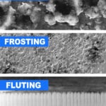
6. Frosting: Frosting appears to be a grey discolored line around all, or part, of the bearing race and evident in both the inner and outer race. Both mechanical wear and EDM can cause that discoloration. Use a microscope to determine whether the line is EDM or mechanically produced.
If the motor was operated by a VFD with no bearing protection installed, there is a high likelihood that the frosting is from EDM.
Fluting Damage: Identified by a distinctive washboard or picket fence pattern. This washboard pattern is called fluting. Fluting can be seen using the naked eye or with 10x magnification.
Take care to identify the correct electrical fluting damage using the observed damage. Sometimes fluting is confused with mechanical bearing damage such as brinelling or false brinelling.
Besides using these recommended practices, please refer to other procedures and bearing failure analysis experts to determine the root cause of the failure.
And always install a new AEGIS Shaft Grounding Ring whenever replacing bearings on an inverter-driven motor. AEGIS Rings have a 2-year extended warranty against bearing fluting damage. No other form of shaft grounding offers a warranty like this.
To learn more about AEGIS shaft grounding and best practices for electrical bearing protection, sign up for a training. We offer monthly live training webinars, and – pandemic restrictions permitting – we can also visit your facility to review your exact application.
Motor Bearings: Electrical Damage Simplified – A Further Examination and Clarification
The article below corrects and adds to the EASA Current’s article from the Dec 2017 issue: “Motor bearings: Electrical damage simplified.”
An article on electrical bearing damage recently appeared in EASA Currents Magazine. While it raised a lot of good points, it also contained information on shaft grounding practices and shaft grounding rings which need correction or further examination. As we discuss electrical bearing damage, please note that we are referring to motors operated by variable frequency drives (VFD).
The title of the article was “Motor bearings: Electrical damage simplified.” True to this title, the article tries to stay as “nontechnical” as possible. Unfortunately, staying “nontechnical” is not always desirable since a thorough understanding of bearing currents and solutions is critical for successful repairs. As the inventors of conductive microfiber shaft grounding rings – the AEGIS® products – we’ve been discussing electrical bearing damage and its solution for over twelve years. It is my opinion that in trying to keep it simple, the article sometimes oversimplifies the problem.
When talking about shaft grounding, it is a mistake not to differentiate capacitive shaft voltage discharge currents (EDM currents) and circulating currents (be they low or high frequency). The author states that his preferred method of bearing protection is to “break the electrical circuit on the opposite drive end (ODE)” of the motor, and install shaft grounding at the drive side. 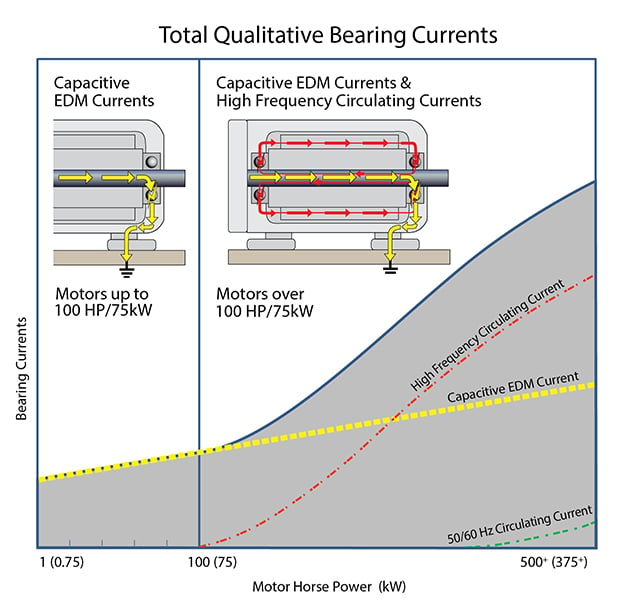 This mirrors our recommended approach for AC motors over 100 HP and for all medium voltage motors. However, circulating currents are not an issue in small AC motors (under 100 HP), so bearing insulation is unnecessary for them and adding a shaft grounding ring to the DE or NDE is sufficient to protect the motor’s bearings.
But the author then states that “if the [shaft] voltage can be clamped low enough with just a grounding brush, the ODE insulation is not always necessary.” This is false. Shaft grounding cannot prevent circulating currents. So, 100 HP+ and medium voltage motors would still be at risk of circulating currents. These motors will always need both shaft grounding (preferably the drive end), and some type of insulation at the opposite end (preferably the ODE).
There is another confusing or confused statement about circulating currents in the same paragraph: “This looping is also the reason [not to] install shaft grounding on the ODE as the loop can extend into the driven machine” and thereby damage its bearings. This is easily misconstrued to mean that shaft grounding should never be installed at the ODE. But it is important to know that this applies only when circulating currents are a potential problem, i.e. motor over 100 HP and medium voltage motors.
When discussing circulating currents potentially extending “into the driven machine” we advise referring to the IEEE 112 which recommends insulating the NDE to avoid a circulating current path in the driven machine. Last but certainly not least, it is important to remember that installing a shaft grounding ring on the DE is still necessary to prevent capacitive voltages from causing EDM damage to the steel (non-insulated) bearing and/or going down the shaft to the driven equipment.
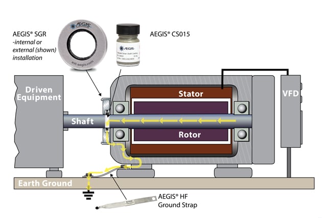
Motor under 100 HP only needs a shaft grounding ring to protect the bearings.
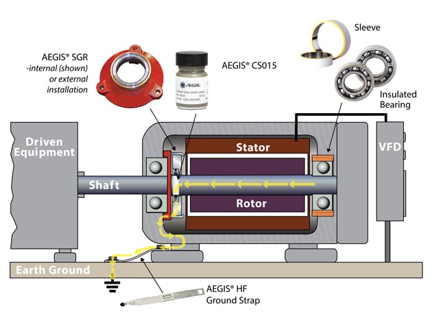
Motor over 100 HP and need insulation (NDE) with a shaft grounding ring on the opposite end (DE)
Now for a discussion on shaft voltages: The author gives a maximum safe shaft voltage level of 5 V peak to peak, and correctly points out that there is no universally applicable “safe” level of shaft voltage. In fact, it the peak voltages which harm the bearings so discussing “peak” voltage is key. The NEMA MG1 document gives a range of 10 to 40 volts peak (20 to 80 volts peak to peak) as the shaft voltage level where bearing discharge can occur. But every system is different; every motor in every state of operation will have its own bearing breakdown voltage where discharge through the bearing occurs. With the lack of a consistent safe level across systems, neither peak voltage nor peak-to-peak measurements are a reliable measure of risk.
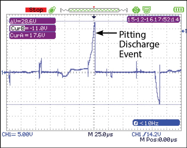
Therefore, we recommend that machine owners or motor repair technicians take shaft voltage readings with a high-speed oscilloscope (at least 100 MHz bandwidth). With this equipment, you can unambiguously tell whether discharge is occurring in the bearings. The smoking gun is a discharge pattern in the shaft voltage waveform (a slow voltage buildup followed by a rapid transition down).
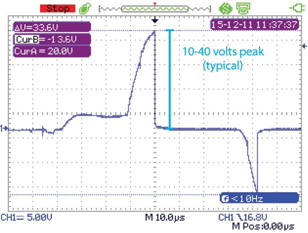
While the article recommends shaft voltage testing, it only recommends measuring peak-to-peak voltage, even though it is not the most important measure. The sample shaft voltage reading in the article has a timescale of 2 ms/div, which is far too long to detect discharges, which occur on a timescale of microseconds. More on this in the Bearing Protection Handbook.
The shaft grounding ring section starts off well, but goes awry in the second sentence by referring to “the standard single row ring.” This refers to the AEGIS® SGR, for low voltage motors, but SGRs have two rows of conductive microfibers, not one. Next the article states that the standard SGRs are “usually” sufficient for smaller motors, but “may not always provide a low enough resistance circuit [sic] to ground.” An SGR with two fiber rows is extremely effective and is proven in millions of applications worldwide on low voltage motors under 500 HP (and as noted earlier, motors over 100 HP also need bearing insulation in addition to the SGR ring).
The article does better when talking about the six fiber-row AEGIS® PRO Rings, saying “These rings are the best option for the least amount of maintenance.” AEGIS® PRO rings are in fact the best and recommended option for medium voltage motors and LV motors over 500 HP.
The author does seem confused, though, about the purpose of the extra rows of conductive microfibers in the PRO ring. He seems to think the extra rows are to decrease the PRO’s resistance relative to an SGR. But in fact, the extra rows serve to increase current carrying capacity, not resistance/impedance per se. This extra capacity is needed for medium voltage and large low voltage motors (500 HP+) because they have higher shaft currents and the PRO ring’s extra rows accommodate that increased current.
The article later claims that “they can be susceptible to wear, heat, and grease contamination.” It is unclear whether “they” refers to PRO rings or SGRs, but the claim is inaccurate for either product. Any properly installed AEGIS® ring is not susceptible to wear. It is designed as a “wear-to-fit” device; the fibers slowly wear until they just-touch the shaft surface, a process which can take 200,000 hours or more. Electrical contact is maintained, by physical contact and near-contact electron transfer, so the ring does not stop working. As for heat tolerance, the manufacturer spec states that AEGIS® rings can withstand temperatures up to 410° F (210° C), and we know of at least one customer who uses AEGIS® rings in an oven at 400 degrees.
As for grease, the AEGIS® fibers cut through and tolerate light grease, but this is a moot point. As the article mentions, AEGIS® rings can be mounted inside motors, away from external grease and grime, and this is where motor repair shops should install them. One bit of information the article left out is that there is even a UL-approved process for installing AEGIS® rings inside explosion proof motors, which is unique among shaft grounding technologies.
Now we come to the author’s preferred shaft grounding method, the copper bristle brush. These devices have a few shortcomings that went unmentioned. The brush’s springs may clog and jam, copper is easily oxidized to its nonconductive green/blue oxide, and the shaft can glaze. Also, we are rather skeptical about the use of grease on the brush.
The article only mentions common mode chokes (CMC) briefly, but manages to get a few errors into those three sentences. The most important one to correct is the misleading statement that they “do not always reduce the shaft voltage to a low enough level to eliminate bearing damage.” In fact, common mode chokes barely affect shaft voltage at all and do nothing to eliminate EDM bearing discharges from the capacitive induced shaft voltage. CMCs are just not useful against the shaft voltage discharge currents that shaft grounding protects against. They may be able to reduce high-frequency circulating currents, but CMCs are not as effective as insulating one bearing, as described above. At any rate, common mode chokes cannot take the place of shaft grounding.
All that said, the article ends with some good preventive maintenance advice, including making regular shaft voltage measurements, and advising specifying engineers to call for motors with preventive measures installed. It ends, “Good service centers will identify electrically damaged bearings and strive to recommend the best method to prevent further issues.” We agree wholeheartedly. Bearing inspection is required by the ANSI/EASA Standard AR100-2015, and by the EASA warranty checklist, and is also one of the processes required of accredited EASA motor repair shops.
Ultimately, this article was written to educate motor repair shops and more importantly, to help them improve their processes and so improve their business. We agree with these goals and hope that the original article succeeds in encouraging an enlightened discussion and seeking the most accurate information when considering bearing protection. And we hope that this article, too, will help advance those goals.
To Prevent Bearings from Failing Again, Find Why They Failed in the First Place
 The new motor you installed 6 months ago is making the kind of noise you only hear in horror movies. So, you purchase and install a replacement motor, hoping that it will not suffer the same fate.
But you’re not really sure what killed the original motor. The best way to determine the cause of the motor’s failure is to perform an autopsy on it. This includes cutting the motor bearings to see what happened to them.
Determining the cause of bearing failure can inform decisions on how to prevent such failures in the future and increase the reliability of VFD-driven motor systems. Cutting and inspecting motor bearings can provide invaluable information about what caused the damage to them. In fact, ANSI/EASA AR100-2015 recommends cutting and inspecting the bearings for evidence of EDM discharges whenever a VFD-driven motor is being repaired.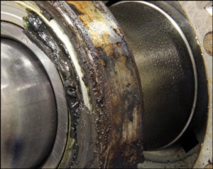
- Start by inspecting both bearings — inside and outside — for contamination, signs of excessive heat, hardening of grease, color of grease (look for abnormal coloration, e.g., blackened grease), and excess grease or oil escaping the bearing. Remember to save a sample of the lubricant for analysis.
- Then, after removing the seals or shields, cut the outer race in half. Follow all established safety precautions and use personal protective equipment including eye protection, hearing protection, a face shield, gloves, and protective clothing.

- Inspect the grease and look for any contamination in the bearing. Burnt grease is typically a sign of continuous electrical arcing in the bearings that heats the oil component of the grease beyond its temperature capacity, causes rapid deterioration of the grease’s lubricating capability, and results in bearing race damage. Arcing also loosens small particles of metal from the ball bearings and bearing races. These particles are abrasive and will cause premature wear to bearing surfaces.
- Clean bearing components with a degreaser or solvent.
- Inspect bearing components for evidence of electrical discharge machining (EDM). Each time the electrical voltage overcomes the dielectric of the bearing lubrication, it arcs through the inner race and through the rolling elements to the outer race, blasting tiny pits in the bearing surfaces. These pits are typically 5-10 microns in diameter, and can be easily seen under a microscope.
- Look for frosting of bearing surfaces. To the naked eye, frosting appears as a discolored grey line around all or a portion of the inner or outer bearing race. It is actually the result of millions of tiny pits, marring the race surface. Since it can be caused by mechanical wear as well as EDM, discoloration should be examined under a microscope to determine its actual cause. If the motor was controlled by a VFD, there is a high likelihood that the frosting was due to EDM.
- Look for fluting damage. Fluting is a distinctive washboard-like pattern on the inside of the outer bearing race that results from the operational frequency of the VFD. Fluting is visible to the naked eye or can be seen with 10X magnification. Since fluting is sometimes confused with mechanical bearing damage (such as brinelling/false brinelling), careful consideration should be given to electrical fluting when assigning a cause to the bearing damage.
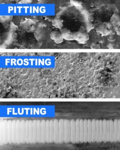
AEGIS Rings also come with a 2-year extended warranty against bearing fluting damage. No other form of protection against VFD-caused bearing damage offers a warranty like this.
To learn more about AEGIS shaft grounding and best practices for electrical bearing protection, sign up for a training. We offer monthly live training webinars, and – pandemic restrictions permitting – we can also visit your facility to review your exact application.
AEGIS Rings Outperform Carbon Brushes
Recently, one of our salespeople pointed out an ad for carbon brushes in a trade publication. The ad made the bold claim that these brushes are “The Industry’s BEST Grounding Solution”. While it makes for great advertising, the claim requires detailed scrutiny.
Rather than get into the specific details on which the brush manufacturer based its claim, we think it makes sense to compare carbon brushes to AEGIS® Shaft Grounding Rings across a full range of performance criteria.
Grounding Effectiveness
While carbon brushes provide adequate shaft grounding for DC 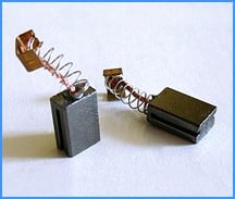 motors (and low-frequency currents), they are far less effective for the high-frequency currents found in inverter-fed AC motors. Due to their very small surface contact (less than 4% of the shaft’s circumference), current does not flow uniformly across the brush surface. It flows through a series of very small contact spots, leading to high impedance and hotspotting.
In contrast, AEGIS Rings have hundreds of thousands of shaft contact points spread 360 degrees around the shaft. By maximizing the contact area, AEGIS Rings maximize the high-frequency discharge capability for VFD-induced voltage.
Hotspotting & High Wear
Since current does not flow uniformly across carbon brushes’ contact faces, they are susceptible to “hotspotting”. Current passes only in very small areas at any single point in time, so the high current density of these discharges generates very high temperatures (hotspotting) that lead to high brush wear. 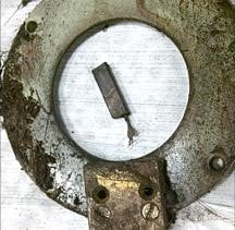 With AEGIS Rings, the hundreds of thousands of contact points spread around the shaft circumference transfer current evenly, eliminating hotspotting and the excessive, nonuniform wear they cause.
Carbon brushes work only when they are in physical contact with the motor shaft. The specially engineered conductive microfibers of AEGIS Rings, however, have unique mechanical and electrical characteristics that ensure effective electrical contact with the motor shaft — even if physical contact is broken. Their patented Nanogap technology maintains electrical contact with the shaft across gaps from 2 nm to 5µm.
Carbon brushes are only effective for DC motors and low-frequency currents. AEGIS Rings, however, are specially designed to protect motors against high-frequency discharges, up to the kHz and MHz range, as produced by VFDs.
Surface Rate:
While high surface rates produce faster wear of carbon brushes leading to more frequent replacements, the effectiveness of AEGIS Rings has been proven in testing at surface rates greater than 180 ft/second and 50,000 RPMs. Spring energized carbon brushes wear quickly and lose contact with the shaft without maintenance or replacement. AEGIS microfibers however have virtually zero friction in contact with the shaft, and even at high rotational speeds AEGIS Rings can be expected to outlive the bearings.
Tolerance to Environmental Conditions:
Environmental conditions such as temperature, humidity, and the pressure of the brush against the motor shaft can limit the effectiveness of carbon brushes. In fact, even the build-up of carbon from the brush itself on the surface of the shaft can create a highly resistive film that can interfere with the brush’s grounding effectiveness for high-frequency shaft voltage.
Carbon brushes are also sensitive to humidity to maintain a conductive patina on the motor shaft. Too little humidity and the carbon dust won’t stick to the shaft, leading to higher friction, brush vibration, and faster wear. Too much humidity can lead to an overly thick film, which can cause grooves in the brush, further reducing its contact with the shaft and lessening its effectiveness.
Carbon brushes are also easily fouled by dirt, dust, grease, and other contaminants that can jam spring-loading mechanisms or disrupt electrical contact between the shaft and the brush.
AEGIS Rings, on the other hand, provide the highest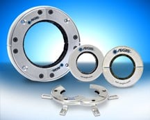 level of resistance to contaminants of any shaft grounding technology. Their microfibers are designed to “sweep” contaminants away from the shaft to maintain contact. And installing the ring inside the motor provides added protection from contamination, for the longest lasting and highest performance possible in highly contamination-prone applications.
Service Life:
Due to wear, carbon brushes require periodic replacement over the course of the bearings’ lifetime. But AEGIS Rings are designed to last for the full L10 life of the bearings, due to AEGIS microfibers’ special design.
The microfibers are designed for minimum wear and maximum conductivity. After 10,000 hours of testing, the fibers showed wear of less than 0.001″ and are projected to last over 200,000 hours of continuous operation and to withstand 2 million reversals. Even when the fibers are worn down to fit the shaft exactly, AEGIS Nanogap Technology ensures that the fibers continue to work by non-contact electron transfer.
Finally, since they last for the L10 bearing 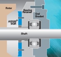 life of the motor and they do not generate any dust or contamination, AEGIS Rings can be installed inside motors — they can be bolted to the back of the bearing retainer. Internal installation will not interfere with the operation of the motor or the AEGIS Ring’s performance, yet offers an extra measure of protection for the ring itself.
AEGIS Rings just work. So for the world’s most effective bearing protection — regardless of motor size, horsepower, speed, or service requirements (stops/starts/reversals) — insist on AEGIS Shaft Grounding Rings, proven in millions of installations worldwide.
For a technical bulletin comparing the effectiveness of carbon block brushes to that of AEGIS Rings, click here.
For our IEEE paper on AEGIS Rings, Design Aspects of Conductive Microfiber Rings for Shaft Ground Purposes, click here.
Washdown Motors Need AEGIS Bearing Protection
Washdown motors are specially designed and built to survive the contaminants, humidity, high-pressure spray, and cleaning chemicals of washdown environments. They are well-protected against threats from the outside that could damage them. But many washdown motors are less-protected against threats from the inside — threats like VFD-induced bearing damage.
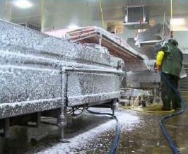
By controlling the speed of motors, VFDs provide a flexible, cost-effective means of controlling processes. But VFDs can also damage motors. VFDs induce voltages on the shafts of the motors they control. Without effective bearing protection, these voltages can discharge through motor bearings (and often through the bearings of pumps, compressors, fans, conveyors, and other coupled equipment), destroying them in as little as a few months.
And since many washdown motors are used in continuous processing applications such as food, chemicals, pulp and paper, blast furnaces, wastewater treatment, metal smelting, natural gas processing, etc., replacing a motor with damaged bearings may require shutting down an entire production line or facility, costing hundreds of thousands, or even millions, of dollars in lost production. In the case of food processing, such shutdowns require the disassembly, cleaning, and sterilization of machinery before the line is restarted to prevent bacterial contamination of the food being processed. This further adds to the length and cost of these shutdowns.
AEGIS® Shaft Grounding Rings protect motors from VFD-induced bearing damage. AEGIS rings install around the motor shaft, with their conductive microfibers in contact with the shaft. These microfibers divert damaging currents away from bearings and safely to ground, and are proven to withstand over 200,000 hours of continuous operation. They are locked securely in place by AEGIS’s patented, protective FiberLock™ channel, which helps protect them from excessive dirt, oil, grease, and other contaminants.
For convenience, AEGIS rings are usually installed externally (on the motor’s faceplate). But for washdown applications, installing the rings inside the motor (on the bearing retainer) affords an extra measure of protection against high-pressure spray. If an AEGIS ring must be installed externally on a washdown motor, we recommend protecting it with an O-ring or V-slinger.
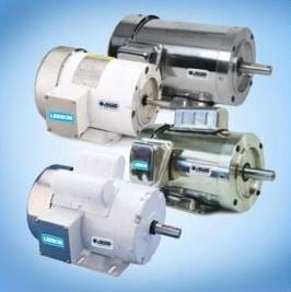
The easiest way to protect a washdown motor against VFD-caused bearing damage is to make sure it comes with AEGIS shaft grounding factory-installed. LEESON recently introduced its new line of Extreme Duck Ultra Washguard™ Industrial-Duty Washdown Motors with AEGIS Shaft Grounding Rings installed internally. For more information on these motors, click here.