

Author: AEGIS
Why VFD-Controlled Motors Need Shaft Grounding
Premature failure can be a real problem in an AC motor equipped with a variable frequency drive (VFD), largely due to motor bearing failure. Yet VFDs have been promoted by engineers, facility managers, building owners, and other stakeholders as devices that help ensure greater energy efficiency while also complementing the workings of automated machinery. VFD technology is one of the greener motor-related technologies used today, allowing users to control the motor’s torque and speed. VFDs can reduce power consumption for an electric motor by 30 percent or more, though the motors need extra protection to keep them from failing prematurely.
Problems Inherent in VFD-Motor Systems
The reason modern AC motors equipped with VFDs are more prone to bearing damage is the drives’ use of three phase pulse width modulation, which produces stray voltage within the motor. This includes voltage on the motor’s shaft, leading to a harmful voltage across the bearings and the risk of electrical discharge if the voltage exceeds the grease’s breakdown voltage. Such discharge causes cumulative damage to the motor bearings.
Importance of Shaft Grounding Protection
These discharges cause electric discharge machining (EDM). While EDM is useful as a machining technique for hard metals, it shortens the life of electric motor bearings, reducing their reliability. To control switching, most VFDs use pulse width modulation to simulate a sine wave at the chosen frequency, assisted by insulated gate bipolar transistors.
The output from these drives creates a voltage on the motor shaft electrostatically, caused by the fluctuating common mode voltage (the average of the three-phase voltages). The voltage induced on the shaft tends to discharge through the bearings, resulting in bearing damage by EDM. Each discharge produces a microscopic pit. Over time, a concentrated kind of pitting known as fluting may develop. With a distinctive washboard pattern, fluting produces excessive vibration, noise, and heat when the motor runs. Once fluting has developed, bearing failure is imminent.
Bearing failure leads to an increase in operation costs due to:
- Increased downtime
- Lost productivity
- Missed deliveries
- Reduced operating efficiency
- Unplanned outages
Measuring Shaft Voltage
Motors can be checked for destructive levels of shaft voltage using a digital oscilloscope. A multimeter (analog or digital) cannot be used, because shaft voltage buildup and discharge happens too rapidly for a multimeter to measure accurately. Only an oscilloscope with bandwidth 100MHz or higher can accurately measure shaft voltage, allowing the user to tell whether the level is high enough to cause electrical bearing damage and potential premature failure.
How Shaft Grounding Rings Protect Motor Bearings
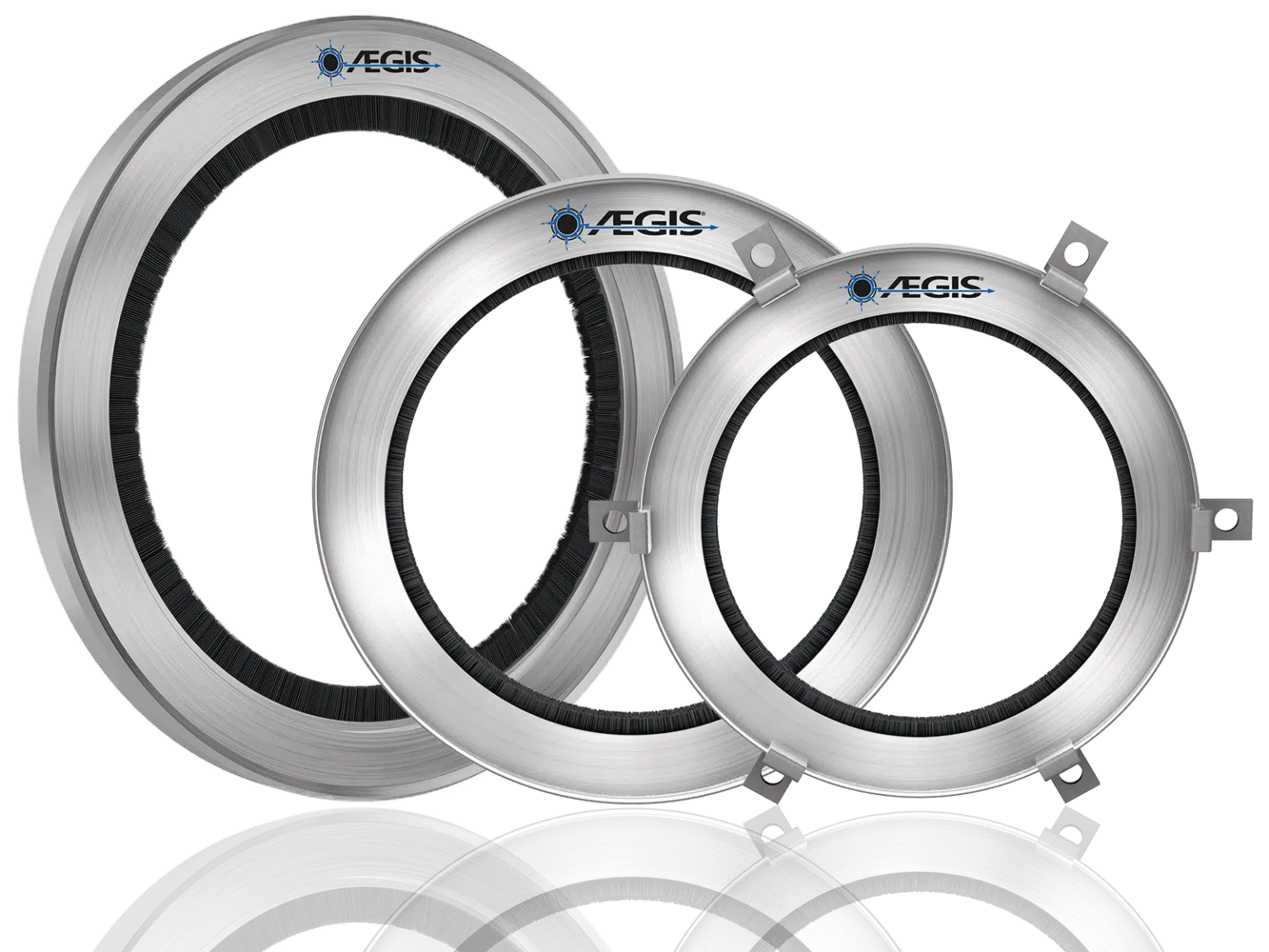
Shaft grounding is one strategy to control this damaging voltage, which can otherwise lead to bearing and motor failure. One particularly effective means to protect against this bearing damage involves installing grounding rings of conductive microfibers around the shaft.
Without a shaft grounding ring or other protection, shaft voltage will discharge through motor bearings or attached equipment to the motor frame and then continue to the (electrical) ground. Shaft grounding rings protect motor bearings by providing an alternative path to ground for charge from the shaft. Rather than going through the bearing, the current goes through the ring to the motor frame.
Current Protections for VFD-Equipped Motors
Most manufacturers offer what’s known as “inverter-rated, inverter-duty, or inverter-ready” electric motors, implying that these motors are already protected from damage due to harmful VFD-sourced voltage. Inverter-rated motors do include protections for the motor windings from the effects of VFD output, as required by National Electrical Manufacturers Association (NEMA) MG1 Part 31 guidelines. This protects the motor against premature failure due to winding damage.
However, this does nothing to protect bearings against damage from EDM. To more fully provide protection, motors controlled by VFDs need to be equipped with circumferential microfiber shaft grounding rings. Motor manufacturer warranties usually only cover the bearings for 90 days. Their logic is, if the bearing is defective, it will fail quickly. But fluting usually takes longer than three months to develop. Fortunately, Electro Static Technology – the manufacturer of AEGIS(R) Shaft Grounding Rings – offers an extended two-year warranty against fluting damage on motors with AEGIS rings installed.
Minimizing Damage
To mitigate electrical damage to bearings and keep VFD-driven motors and their associated systems running reliably, protective motor shaft grounding rings featuring conductive microfibers are necessary. Motor manufacturers can install this technology inside or outside the machine during fabrication, and retrofitting is also possible. However, when purchasing an electric motor, buyers should pay close attention to ensure it has the right protection.
Most original equipment manufacturers (OEMs) of electric motors provide product lines with factory-installed shaft grounding rings to protect from fluting, along with the required inverter protections. It’s important to ask an OEM before purchasing whether their motors offer this level of protection against damage by VFD control. To ensure that a new motor will provide trouble-free operation, it’s important for the buyer to specify that they require circumferential microfiber shaft grounding on any motors within machines that use pulse-width modulated VFDs.
To learn more about AEGIS shaft grounding and best practices for electrical bearing protection, sign up for a training. We offer monthly live training webinars, and we can also visit your facility to review your exact application.
How Do I Find the Part Number of an SGR for My Motor?
We have written about choosing a mounting style for AEGIS® Shaft Grounding Ring – here, here, and here. But once you know what mounting style you want, how do you get the rest of the part number? That’s where our catalog‘s Product Selector comes in.
The AEGIS Product Selection Guide
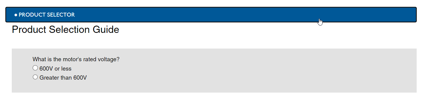
The AEGIS Product Selector will walk you through the entire process of finding a part number based on the motor’s attributes. You can use the Product Selector if the motor’s
- Voltage rating is under 600 V
- Input current type is AC
- Power rating is under 500 hp/ 350 kW
If the motor is a standard NEMA or IEC frame size, you can easily choose a uKIT based on the frame size’s U value (for NEMA frames) or D value (IEC frame).
For nonstandard frame sizes, or if you don’t know the frame size, the selector will show you exactly what measurements to make on the motor shaft.
At the end of it all, the Selector will take you to an SGR family page, where you will find the part number you need based on the mounting style you want.
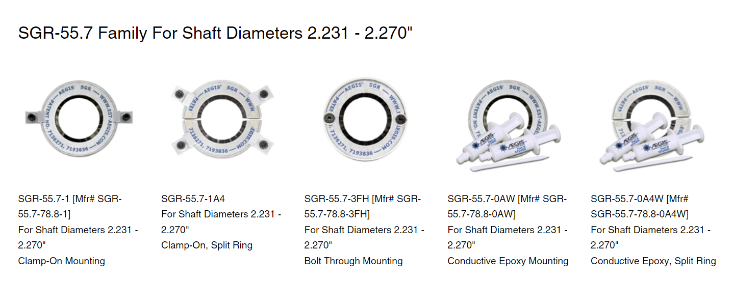 It’s as easy as that! You can check out our AEGIS Part Selector at catalog.est-aegis.com.
AEGIS Rings come with a 2-year extended warranty against bearing fluting damage. No other form of protection against VFD-caused bearing damage offers a warranty like this.
To learn more about AEGIS shaft grounding and best practices for electrical bearing protection, sign up for a training. We offer monthly live training webinars, and – pandemic restrictions permitting – we can also visit your facility to review your exact application.
Renewable Energy Industry: Motor Bearing Performance and Reliability
The use of renewable energy has increased rapidly over the past couple of decades, with wind, solar, geothermal, and other power sources at the forefront of today’s sustainable energy solutions. Like any other industrial sector, the renewable energy industry relies heavily on electric motors to power equipment like pumps and ventilation systems. Such equipment used in the transport and processing of materials and running of power-generating facilities for the renewable energy industry depends in part on the performance of electric motors to create clean, sustainable electricity.
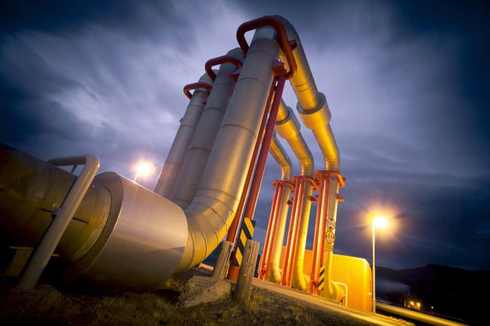 Like any machine used in industry, motors are assembled from components. When any of these components fail, it can affect motor performance, often resulting in motor failure and unplanned downtime. Not only is this expensive, but it also disrupts power generation, which is even more expensive. Motor bearings are particularly vulnerable, so many traditional power generating plants and those used by the renewable energy industry utilize bearing protection to protect motor performance. One way to optimize motor performance and protect bearings is by utilizing shaft grounding rings to protect motor bearings from electrical damage.
Why Motor Performance is Important to the Renewable Energy Industry
A major portion of energy used globally by many industries goes into running electric motors, so motor performance and efficiency is of utmost importance, including in the renewable energy industry. Many energy savings strategies involve using variable frequency drives (VFDs) and high-efficiency motors to improve efficiency and motor performance to reduce wasted energy. Numerous regulations and incentives have encouraged greater energy efficiency throughout many industries. These have followed exhaustive research and testing to promote energy-saving strategies that make economic sense. The renewable energy industry is no exception, with biomass, geothermal, and other renewable generation facilities employing VFDs to improve motor performance and optimize power generation.
Variable Frequency Drives
In a chapter on induction motors published by IntechOpen in 2023, the author notes several studies that look into decreasing industry operating costs using more efficient motors. This includes a study by the National Renewable Energy Laboratory (NREL) that found replacing standard motors with high-efficiency motors can reduce energy consumption by as much as 40 percent. VFDs can limit motor speeds to go no faster than the application demands, thus saving energy. The author also cited a Department of Energy (DOE) report noting that savings of up to 50 percent could be achieved using VFDs to augment high-efficiency motor performance.
VFDs are the descendants of the variable speed drives (VSDs) from the 1980s, built upon the century-old three-phase AC induction motor. The induction motor was more efficient than DC models, but controlling AC motor speed wasn’t possible until the invention of VSDs. More compact than their VSD ancestors, today’s VFD technology has allowed considerable precision in varying AC motor speeds while allowing motor control when running in both directions. Though VFDs offer little benefit for applications that don’t depend on motor speed control, they have revolutionized motor performance and significantly decreased motor energy use.
VFDs & Bearings
As revolutionary as VFDs are, electric motors driven by them suffer more bearing damage. This is due to a voltage buildup, caused by VFD control, that discharges through the bearings. This damages the bearing surfaces and degrade lubricants. As it progresses, this damage causes vibrations leading eventually to bearing failure. Not only does this affect motor performance, but premature bearing failure limits productivity and increases downtime.
Case Studies: AEGIS®️ Shaft Grounding Rings for the Renewable Energy Industry
As more conventional power plants like coal, natural gas, and nuclear seek to make themselves more efficient, so does the renewable energy industry. Industry experts on power generation have developed two complementary ways in which to stem electrical bearing damage resulting from the use of VFDs.
The first method ensures that current from the shaft can reach ground without going through the bearings, which can be accomplished with a shaft grounding device like the AEGIS®️ Shaft Grounding Ring. The second method involves installing insulated bearings to prevent voltage from discharging through the bearings. These methods accomplish the same thing, with the insulated bearings capable of being combined with a grounding ring for even greater protection.
Geothermal Energy
Most often, energy generated through solar panels or wind turbines is the first type of power generation thought of as renewable. The energy industry utilizes both sources to produce sustainable electricity, though they won’t produce power at times when the sun doesn’t shine or the wind doesn’t blow. The renewable energy industry also involves geothermal plants, which generate electricity by harnessing “hot spots” in the Earth’s crust that can produce steam from groundwater.
Though geothermal energy is a very clean energy source, there are few places where it can be profitably harvested. Unlike solar or wind, geothermal energy provides baseload power, which means a geothermal plant can supply electricity continuously. Geothermal plants need to regulate the power generated, which is done partly by using VFD-driven pumps that circulate hot and cold water. Without bearing protection, those pump motors’ bearings would need to be replaced frequently due to electrical bearing damage or total failure.
AEGIS® Shaft Grounding Rings protect bearings in various:
- Auxiliary pumps, such as process, axially split single-stage and segmental ring section pumps
- Circulating water pumps, including vertical wet-pit and horizontal single-stage pumps
- Condensate extraction pumps, including vertical multi-stage canned and vertical turbine canned pumps
- Heat transfer fluid pumps, such as multistage vertical pumps, overhung process pumps, and pumps used for secondary recirculation
- Production well pumps like vertical deep well line shaft pumps
- Re-injection well pumps work in high-pressure environments, such as axially split single-stage, process booster, and multi-stage barrel re-injection pumps
Millions of AEGIS® Rings have been installed globally to improve motor performance and increase bearing lifespan, including for VFD-driven pumping systems providing geothermal energy for the renewable energy industry.
At Electro Static Technology, we are so confident in AEGIS Rings that we offer a 2-year extended warranty against bearing fluting damage. No other form of shaft grounding offers a warranty like this.
To learn more about AEGIS shaft grounding and best practices for electrical bearing protection, sign up for a training. We offer monthly live training webinars, and we can also visit your facility to review your exact application.
The Cost of Unplanned Production Downtime
 In manufacturing, unplanned downtime costs are huge and only getting more significant. According to a recent study of 72 large companies by Senseye Predictive Maintenance, large plants’ costs of unplanned downtime average $532,000 per hour. The study cites the disturbing figure that downtime costs these companies 11% of their annual revenue in 2022, up from 8% in 2020.
What Are Manufacturers Doing to Mitigate Unexpected Downtime?
It goes without saying that manufacturers do all they can to minimize unplanned downtime. There are many components to a downtime mitigation strategy, ranging from beefing up maintenance programs to investing in protective products to make manufacturing systems as reliable as possible.
Protecting Motor Bearings From Damage by VFDs
One step in this direction is to protect electric motor bearings against the damage caused by variable frequency drive (VFD) control. VFDs generate high-frequency voltage on the shafts of the motors they control. Without protection, this so-called shaft voltage will discharge through the motor or system bearings, causing electrical damage, eventual premature failure, and potentially unplanned downtime.
A Reliable Strategy: Shaft Grounding Ring
One protective product is the AEGIS® Shaft Grounding Ring. AEGIS rings provide a low resistance path to charge on the shaft and bleed down the shaft voltage to levels too low to arc through the bearings, protecting them from discharge damage. When protected by AEGIS rings, VFD-controlled systems are less likely to fail prematurely, and one risk of unplanned downtime is thus mitigated.
While AEGIS rings alone cannot prevent every motor failure, they are an important part of the overall reliability strategy for every plant that uses VFDs for motor control.
AEGIS Rings also come with a 2-year extended warranty against bearing fluting damage. No other form of protection against VFD-caused bearing damage offers a warranty like this.
To learn more about AEGIS shaft grounding and best practices for electrical bearing protection, sign up for a training. We offer monthly live training webinars, and – pandemic restrictions permitting – we can also visit your facility to review your exact application.
FAQ
Q1. What are other causes of unplanned downtime, not involving VFDs?
A1. Not all bearing failure is caused by VFDs. Contamination (in unsealed bearings) is a common cause of failure. Other system components can also fail. Often, the cause is human error – misalignment of components, errors in control programming, and failure to notice or respond to small problems that spiral. Supply chain disruptions and unpredictable events like power outages and extreme weather also contribute to unplanned downtime. The key to minimizing unplanned downtime is to focus on what can be predicted or protected against.
Q2. How effective at preventing bearing failure are AEGIS rings?
A2. When installed properly, AEGIS rings effectively lower shaft voltage, protecting against bearing failure due to electrical damage, and reducing the total risk of unplanned downtime. However, they do not protect against circulating bearing current in larger motors (over 100 hp/75 kW) – For circulating current, you need either bearing insulation or VFD output filters to mitigate damage. And AEGIS rings – or any electrical bearing protection – cannot prevent bearing failure due to non-electrical damage like excessive vibration from misalignment.
Q3. What other strategies or protective measures besides AEGIS rings can manufacturing plants employ to mitigate the risk of unplanned downtime related to VFD-controlled systems?
A3. Besides AEGIS rings, other protective measures may include: regular equipment inspections and maintenance, implementing condition monitoring and predictive maintenance programs, investing in high-quality VFDs with built-in protective features, using proper grounding and bonding techniques, and providing comprehensive training for operators and maintenance staff to ensure proper handling and troubleshooting of VFD-related issues. Combining multiple layers of protection and proactive maintenance practices enhances the reliability and resilience of manufacturing systems against unplanned downtime.
How Shaft Grounding Devices Are Actually the Economical Solution
Shaft grounding devices help minimize voltage on a motor’s shaft, preventing damage caused by current flowing through the vulnerable bearings of the motor. Voltage on the shaft can occur due to friction building up a static charge, from induction, and from leakage from within the system. Shaft grounding devices keep voltage from discharging through motor bearings by providing another, lower resistance route for the current. By creating an alternate path of least resistance, shaft grounding devices divert electricity away from components that could be harmed by this current, saving the expense of repair or replacement and the much larger potential expense of unplanned downtime.
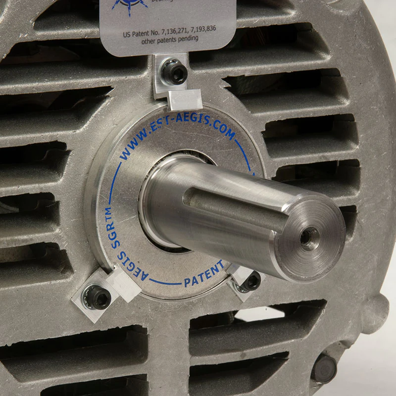 The US Department of Energy (DOE) conducted influential studies to understand how to conserve energy in commercial and industrial motors. These studies emanated from the Motor System Market Assessment (MSMA), which began in 2016 to study motor systems in the US industry. The third volume of this report came out in 2022 and looked into improved savings due to greater energy efficiency in industrial and commercial motors. For more reading on this topic check out the following blogs:
The Importance of Shaft Grounding Devices for Motors
Quantifying savings due to energy efficiency and easier maintenance contributes to understanding the costs of owning and operating electric motors. Over the course of a motor’s lifetime, about 20 years, electricity makes up about 90 percent of the total cost of the motor. Increasing energy efficiency can lower these costs by as much as 30 percent. The rest of the costs a company bears include the initial cost of the motor, downtime for maintenance, and the price of rebuilding the motor.
An assessment by Electro Static Technology shows how these expenses play out when variable frequency drives (VFDs) are used to control motors instead of direct on-line control. Some of the savings from energy efficiency are eaten up by the cost of the VFD itself, along with higher downtime and rebuilding expenses. However, when a shaft grounding device is installed in a motor on a VFD, it brings down the cost to the company of any downtime and motor rebuilding expenditures, on top of the energy savings enabled by the VFD.
How Shaft Grounding Devices Protect Bearings
Shaft grounding devices, like the AEGIS Shaft Grounding Ring, protect motor bearings and other sensitive components from electrical damage from voltage discharge. Current follows the least resistant pathway until it reaches the ground. For motors without shaft grounding, the bearings are the path of least resistance and are susceptible to electrical damage. Arcing from shaft voltage discharge causes damage to a bearing, though reducing this discharge with shaft grounding rings makes motor bearing failure less likely.
Shaft grounding rings help to:
- Direct electrical energy away from bearings in a regulated manner.
- Protect bearings, which often offer the best path for electric current.
- Restrict the flow of current passing through other components from the motor shaft.
When bearings wear more quickly than normal, it’s likely that voltage on the shaft is the cause, which shaft grounding rings help prevent.
Bearings will likely show the following signs of damage:
- Pitting
- Frosting
- Fluting
Grounding rings divert electrical current away from internal components within a motor, providing a better path for it to reach the ground, thus preventing the need to replace parts or experience downtime.
Shaft Grounding & Variable Speed Drives
The most recent MSMA report proposed changes stemming from the ongoing promotion of energy efficiency in the industry. This has driven an increase in VFD installations in existing and new motor systems. This is despite VFDs being only about 16 percent of industrial and 4 percent of commercial motor systems as of 2016. VFD capabilities enable adjustment of motor speed so as to decrease energy use.
However, VFDs also have an adverse impact on an induction motor’s roller bearings, a problem referred to as fluting. This phenomenon occurs when grooves form in a bearing, caused by an electric current passing through the bearing from the motor’s shaft. This increases the cost of a VFD-enabled motor over time, as it increases the need for repair due to bearing and motor failure. The good news is that shaft grounding rings can largely prevent this problem. By preventing fluting and the damage it entails, manufacturers can enjoy even greater savings from increasing a motor’s efficiency.
Motors with VFDs are more likely to experience bearing failure, as the input voltage is not balanced. In motors on line power, the sine wave input voltage is balanced voltage, so the motor has no net charge. The voltage, however, is essentially unbalanced for the pulse wave modulated (PWM) waveforms that VFDs generate. This imbalance creates voltage within the motor’s structure, leading to voltage discharging from the rotor to ground through the motor’s bearings.
This may lead to:
- Downtime caused by bearing failure.
- Need for bearing replacement, which requires the replacement or removal and repair of the motor.
Cost-Efficiency of VFDs
Controlling motors with VFDs allows users to control their speed and torque. Considering the current pricing of these systems, some evaluations show their installation is likely to be cost-effective in about three-quarters of industrial and nearly half of commercial motor systems. This translates to savings of up to $4 billion annually by adopting VFD-controlled motor systems. Yet these savings would be partly negated without including shaft grounding rings to protect bearings from failure.
Preventing Bearing Failure
Grounding rings are commonly used to discharge voltage that could otherwise damage the motor bearings. This shaft grounding connects the motor’s turning rotor to earth ground through the motor’s frame. By adding a shaft grounding device before installing the motor, commercial facilities can save not only the expense not only of replacing motors with failed bearings but also lower costs from downtime. In most applications, repair/replacement costs are dwarfed by the cost of unplanned downtime.
The Economics Behind Shaft Ground Rings
The basic economics behind installing shaft grounding devices in motors is sound. These work to proactively lower the risk of costly motor repair due to premature bearing failure and resulting motor-related downtime. In fact, they’re used as cost-effective solutions in multiple industries and applications that utilize motors.
Shaft grounding rings are used for industries and in applications that include:
- Automation systems for pumps and other industrial machinery
- Cement industry
- Cleanrooms in pharmaceutical industry
- Conveyors and braking motors in distribution centers
- Cranes in ports for unloading cargo
- Gas turbines
- HVAC industry
- Marine industry
- Oil and gas industry
- Paper processing industry
- Plastics manufacturing
- Power generators
- Steel manufacturing
- Testing equipment
- Wind generators
Shaft grounding rings often outlast the motors in which they’re installed and are renowned for their ability to withstand adverse conditions. Many shaft grounding rings come with stock kits that enable them to fit into most standard motors, even with a variance in the shaft size. Grounding devices also allow for easy installation and maintenance.
At Electro Static Technology, we are so confident in AEGIS Rings that we offer a 2-year extended warranty against bearing fluting damage. No other form of shaft grounding offers a warranty like this.
To learn more about AEGIS shaft grounding and best practices for electrical bearing protection, sign up for a training. We offer monthly live training webinars, and we can also visit your facility to review your exact application.
Four Reasons to Buy Motors with AEGIS Installed
 AEGIS® Shaft Grounding Rings offer essential protection against electrical bearing damage for motors on VFDs. AEGIS rings can be retrofitted to in-service motors, but the best way to get AEGIS protection on your motor is probably to purchase a new motor with AEGIS factory-installed. Here are four reasons why.
4 Reasons to Buy Motors with AEGIS Rings Installed
1. It saves time:
Buying a motor with an AEGIS ring factory-installed saves you the time of finding the right grounding ring for your motor, and the effort of installing the ring. Offerings vary by motor manufacturer and product line, but AEGIS is available both standard and as a mod.
2. It saves money:
The cost of a motor with AEGIS already installed is less than the cost of the motor and ring separately. On top of this, you save the cost of installation.
3. No risk of improper installation:
Major motor brands like Baldor (ABB), U.S. Motors (Nidec), Marathon, LEESON, WEG Electric, and G.E. Industrial Motors have installed hundreds of thousands of shaft grounding rings in their motors. They know exactly how to install AEGIS rings according to our best practices. As an added bonus, most motors get the grounding ring factory-installed inside the motor, protecting it from any potential environmental damage or contamination.
4. The AEGIS 2-Year Extended Warranty:
New motors typically come with a one to five-year warranty from the manufacturer. But typically, bearing failure is only covered for a fraction of that time, under the logic that they will fail quickly if something is wrong with the bearings. But this doesn’t take into account the risk of bearing fluting due to VFD-sourced electrical damage, which takes months to years to cause failure. That’s why the AEGIS 2-Year Extended Warranty extends protection against fluting damage for two years after installation. No other shaft grounding device offers a warranty like this.
To learn more about AEGIS shaft grounding and best practices for electrical bearing protection, sign up for a training. We offer monthly live training webinars, and we can also visit your facility to review your exact application.
Key Benefits of Conductive Epoxy
 Different epoxy adhesives are used for various applications, including automotive, consumer electronics, electric vehicle, and fuel cell industries. Conductive epoxy has also increasingly become used in printed circuit boards and other high-tech electronic components. This might include using conductive epoxy in mounting dies and other features onto printed circuit boards, along with their use in liquid crystal displays. Conductive epoxy is often used to replace soldering, which is also used in bonding, brazing, connecting, electrically shielding, fastening, and sealing components, including printed circuit boards. In printed circuit board fabrication and repair, conductive epoxy is most promising.
What is Conductive Epoxy?
Electrically conductive epoxy has two chief purposes. Firstly, like all adhesives, it’s used to form joints to offer sufficient strength and allow the two surfaces to create an effective bond. Secondly, conductive epoxy offers an electrically conductive connection between the two surfaces it joins together. These dual functions are achieved by making epoxy conductive through fillers like carbon black, graphite flakes, and various types of metal particles. These provide the electrical properties for which conductive epoxy is known while also helping components adhere to surfaces in the products in which it is used.
While epoxy alone isn’t conductive, epoxy combined with conductive metals plays a valuable role in many modern electronic products. These metals are combined with epoxy to make it electrically and thermally conductive. Epoxy can thus also help dissipate heat, helping to keep components cooler. The metal within this matrix allows the adhesive to offer highly stable electrical conductivity for products that require such conductive properties.
Materials used to make epoxy conductive include:
- Aluminum
- Carbon
- Copper
- Gold
- Graphite
- Nickel
- Silver
To allow the passage of electric current, conductive epoxy utilizes these highly conductive materials within an epoxy resin.
Uses for Conductive Epoxy
Conductive epoxy is an electrically conductive adhesive comprising conductive particles dispersed within a resin matrix, along with other additives. Because it bonds well with numerous materials while also conducting electricity and heat, conductive epoxy’s properties are excellent for making microelectronic assemblies. Because of the epoxy’s conductivity, it can be used to attach elements, bond wires with tube bases, connect thin wires within printed circuits, plane holes that pass through the printed circuit, and repair holes along with other parts of a printed circuit board.
Common applications for a conductive epoxy include:
- Bonding radio frequency identification tags to items
- Coating plastic boxes containing electronics
- Computer hard drives
- Fixing and grounding samples for scanning electron microscopes
- Grounding or controlling electrostatic discharge
- Heat sinks
- Liquid crystal displays
- Mounting microelectromechanical systems to printed circuit boards
- Repairing printed circuit boards
- Shielding against electromagnetic interference
- Solar cells
Conductive epoxy works much better than soldering for applications with significant risk of thermal and mechanical cracking. This is particularly true when fabricating or repairing printed circuit boards, as their components are sensitive to heat and can be easily damaged when soldered. Additionally, though lead and tin solders have been used effectively for printed circuit boards, lead’s toxicity has caused it to be used less because of its potential to contaminate the environment. Solders that don’t contain lead have a considerably higher melting point, however, which increases the risk of thermal damage during soldering.
Lead-free solders also have less elasticity than those made with lead, producing more brittle joints at greater risk for cracking under stress and at high temperature. As an alternative to solders with and without lead, conductive epoxy considerably lessens the possibility that components sensitive to heat will be damaged during fabrication. This is partly because conductive epoxy cures at low temperatures while offering superior mechanical and thermal stress resilience. Research continues regarding conductive epoxy-based adhesives, including through the testing of various other materials to use as fillers.
Pros and Cons of Conductive Epoxy
Like any material, however, conductive epoxy has its advantages and disadvantages. It works very well in situations where there’s danger of thermal or mechanical cracking. For components made from materials sensitive to heat, substituting conductive epoxy for soldering will make thermal damage less likely. Because of its benefits, conductive epoxy has numerous applications in manufacturing. Yet understanding its drawbacks will help in any decisions regarding any specific application.
Conductive Epoxy Pros
In simple terms, conductive epoxy is just an epoxy glue with particles of metal or conductive carbon interspersed throughout. Due to its makeup, it can be used on surfaces where soldering wouldn’t be effective.
Some specific advantages of using conductive epoxy include:
- Less toxic as it’s made without lead.
- Needs no flux, so is less complicated than soldering.
- No mask or other special equipment is necessary to apply it.
- Provides thermal conductivity to surfaces.
- Resists moisture.
Additionally, most conductive epoxy is compliant with RoHS, a European Union regulatory measure that bans certain substances – like lead – in electrical and electronic products.
Conductive Epoxy Cons
Though there are many advantages to using conductive epoxy, there are also several disadvantages compared to soldering.
These disadvantages include:
- More expensive than soldering.
- Proper conductivity requires that epoxy is thoroughly mixed.
- Setting times are longer.
- Shelf life depends upon proper storage.
Another downside is that conductive epoxy cures without movement, making solder bridges more likely to occur. This can result in components or a trace burning up, short circuits, or general circuit malfunctions.
Conductive Epoxy and Motor Bearings
Conductive epoxy can also play a role in motor bearing protection. It can be used to mount AEGIS(R) Shaft Grounding Rings on motors to safely discharge shaft voltage and electrical bearing damage. In this application, conductive epoxy’s chief advantage is convenience: The user can simply grind away paint on the motor face and secure the shaft grounding ring with the epoxy, rather than needing to drill and tap screw holes in the motor. For more information about AEGIS®️ shaft grounding technology and how to protect motor bearings from electrical damage, contact Electro Static Technology. Check out our product catalog online to learn more about our products, including AEGIS(R) Rings and conductive epoxy.
At Electro Static Technology, we are so confident in AEGIS Rings that we offer a 2-year extended warranty against bearing fluting damage. No other form of shaft grounding offers a warranty like this.
To learn more about AEGIS shaft grounding and best practices for electrical bearing protection, sign up for a training. We offer monthly live training webinars, and we can also visit your facility to review your exact application.
Advantages of Using a Digital Oscilloscope for Shaft Voltage Testing
The digital oscilloscope is an important testing device for accurately measuring voltage signals, largely replacing the analog model.
What Digital Oscilloscopes Measure
 For oscilloscope testing, digital models offer several cutting-edge features that make them easier to use than their analog ancestors, though there are a few drawbacks. Engineers measure voltage waves with the help of an oscilloscope for testing, substantiating, and correcting circuit designs, though they can also be used to test other electronic components. The waveforms are displayed as an (X, Y) graph (usually with time on the X axis and voltage on the Y axis) representing the measured signal.
This graph illustrates attributes of the signal that include:
- Voltage and time measurements of the signal
- Amounts of DC (direct current) and AC (alternating current) in the signal
- Noise within the signal and whether this noise fluctuates over time
- Periodic signal frequency
- Signal distortion that may indicate a component malfunction
Basically, oscilloscope testing helps the user understand how a signal changes over time, with time represented on the horizontal X axis while voltage is represented on the vertical Y axis.
Advantages of Digital Over Analog Oscilloscope Testing For Bearings
Before the arrival of the digital oscilloscope, testing was done with analog models using CRT screens similar to those used in older televisions. Modern digital oscilloscopes feature flat screens that are less expensive, thinner, lighter, and more energy efficient. Due to these advantages, CRTs no longer feature in any current oscilloscope. Testing with digital oscilloscopes provides an almost identical description of voltage over time compared to analog models.
One particularly important advantage of digital oscilloscope testing involves motors running on variable frequency drives (VFDs). Shaft voltage can cause electrical damage to bearings in VFD-controlled motors, causing unplanned downtime due to bearing failure. Often, accurate oscilloscope testing of motor shaft voltage can help prevent this from occurring. It’s best to establish oscilloscope testing early in the operational phase of a VFD-equipped motor, such as after it’s installed or recently repaired.
Accuracy and Precision of Measurements
Testing results are more accurate and precise when comparing a digital to an analog oscilloscope. Before delivery of waveform data, digital oscilloscopes clean up any distortions or other unwanted noise in the measured signal. With higher resolution, digital oscilloscopes can accurately measure both time and voltage. This makes it possible to understand better the risk of bearing failure in a motor.
Processing and Analyzing Signals
When comparing an analog model to a digital oscilloscope, more accurate measurement is but one benefit. More advanced processing and analysis capabilities can be done with digital oscilloscopes. Testing is thus accomplished through the use of several mathematical equations and functions.
Mathematical operations involved in oscilloscope testing include:
- Algorithms like the fast Fourier transform (FFT) for performing a frequency domain analysis
- Augmented triggering selections that capture selected events
- Functions that perform mathematical operations on waveforms
With these capabilities integrated into a digital oscilloscope, testing can incorporate measurements like frequency, peak-to-peak voltage, pulse width, and rise time. Such analysis helps predict more accurately whether and how seriously a motor bearing is at risk of electrical damage.
Recording and Storing Waveform Data
In any sort of oscilloscope testing, the ability to record, store, and replay waveform data makes it more useful. Digital oscilloscopes have more internal memory for data storage, while cloud-based models offer almost unlimited external storage. This permits closer analysis of waveforms while also allowing users to reference a specific reading from an oscilloscope. Testing voltage on motor bearings can thus utilize these saved waveforms for analysis.
Display and User Interface for Digital Oscilloscopes
Ease of use is another factor, with menus in the user interface and often a touch screen featured on a digital oscilloscope. Viewing options include the ability to zoom, pan, or move waveforms easily to focus on particular qualities in the gathered data. These features allow users to adjust the instrument effortlessly, with the simplicity of the process allowing a user to gauge a motor’s shaft voltage or any other signal more effectively.
Limitations of Digital Oscilloscope Testing
While there are many benefits associated with the digital oscilloscope, testing shaft voltage with the instrument does have some drawbacks.
These limitations include:
- Aliasing happens at higher frequencies, occurring when an oscilloscope fails to accurately describe a waveform recording due to not sampling the signal quickly enough, which results in misidentification of the signal frequency; to prevent this, the sampling rate must be double that of the highest frequency part being analyzed
- Constraints on bandwidth can negatively affect the precision of measurements when it comes to higher frequencies; effective bandwidth may also decrease if overly complex signal processing techniques or additional channels are used
- Distortion may occur when the input voltage range is exceeded on a digital oscilloscope; testing some of the stronger signals by digital models is ineffective, though these oscilloscopes tend to have better vertical resolution
- Narrower dynamic range when a digital model is compared to an analog oscilloscope, with testing revealing the extent of signal amplitude readings that describe the system’s range
What is an Oscilloscope Simulator?
Also known as a virtual oscilloscope, these are software applications that simulate the operation of an oscilloscope. Simulators help users better understand how to read the scale screen of an oscilloscope. Simulator software apps also help teach how to test and analyze signals, measure voltage, prototype electrical circuits, check for malfunctions, and conduct other operations by imitating the functions of an actual oscilloscope.
Certain oscilloscope simulators even have capabilities that allow live microphone audio to be used as input signals.
Shaft Voltage Testing With AEGIS® Oscilloscope
The AEGIS® Shaft Voltage Tester™ Digital Oscilloscope provides maintenance personnel a means to quickly determine when there’s a discharge from a motor shaft that could damage the bearings. With a probe that includes special conductive microfiber tips, each scope also features a USB port for saving readings and a case that makes it easily transportable.
For more information about the AEGIS® Shaft Voltage Tester and how it can help with your application, contact us here.
At Electro Static Technology, we are so confident in AEGIS Rings that we offer a 2-year extended warranty against bearing fluting damage. No other form of shaft grounding offers a warranty like this.
To learn more about AEGIS shaft grounding and best practices for electrical bearing protection, sign up for a training. We offer monthly live training webinars, and we can also visit your facility to review your exact application.
3 Factors to Consider With Bearing Performance
 Bearings are an integral part of electric motors. Designed not only to support the rotor, they help maintain a sufficient air gap between the stator and rotor, while also helping transfer the load from the shaft to the motor’s frame. For small electric motors, bearing failure is usually dealt with by replacing the entire motor. With larger motors, replacement is more expensive than repair. So bearing failure often leads to considerable downtime, resulting in an expensive loss of productivity. To keep bearing performance optimal and to prevent bearing failure, it’s highly desirable to use the best quality bearings available, along with protective accessories like bearing seals and shaft grounding rings, so that they’re able to withstand any environmental stresses.
Factors Affecting Bearing Performance
Bearing performance must be sufficient for the motor to work well at both higher and lower speeds, though electric motor designers must also take into account friction to reduce energy consumption. Designers must also consider bearing performance when looking at the requirements for specific motor applications. This often includes determining the limitations of various sizes and types of bearings. Performance should also ensure the design considers economic aspects like the cost of manufacturing and maintenance for a motor.
Poor bearing performance can lead to failure, which can result from:
- Overloading: When subjected to extreme loads beyond the design capabilities of a bearing, performance suffers, and parts wear out more quickly, a result of factors like too much torque, high velocities when in operation, or sudden changes to the load.
- Misalignment: With excessive vibrations caused by misalignment of the bearing, performance suffers and adds to stress on the motor, which can then lead to failure resulting from fatigue.
- Improper lubrication: An insufficient or excessive amount, or poor quality, of lubricant, causes poor bearing performance due to excess friction, which can result in overheating, leading to premature motor failure.
- Improper installation: When not installed appropriately, uneven forces cause excessive loads, resulting in worse bearing performance due to premature deterioration often instigated by overheating.
- High temperatures: When operating, electric motors generate heat that causes thermal expansion and, above a critical temperature, degradation of lubricant, negatively affecting bearing performance and lifespan.
- Electric current: Factors like static, VFD control, and improper grounding can produce stray voltage where it shouldn’t be, affecting bearing performance when the voltage discharges by arcing through the bearings, causing pitting on the bearing’s surfaces and degrading the lubricant.
- Contamination: Debris, dirt, dust, and other contaminants can affect bearing performance by causing greater abrasion and wear.
- Aging: Like any moving component within a mechanical device, bearings are affected by wear due to age, which can lead to heightened friction and higher noise levels, eventually leading to a breakdown.
The three main factors affecting bearing performance are friction, lubrication, and temperature.
How Friction Affects Bearing Performance
Friction causes wear on any moving part within a motor, including bearings. Performance reductions due to friction are only a part of the equation, as too much friction over longer periods can damage equipment and systems extensively. While bearing performance must consider a certain amount of friction when in operation, choosing the right bearings for an application to limit friction is important.
Friction occurs when there’s interaction between components within a bearing. Performance depends on the interactions between the inner race (ring), outer race, retainer, rolling elements, and the seal or shield. Friction occurs whenever the bearing rotates, but there is also static friction when the bearing is at rest. The torque necessary to overcome this static friction to begin rotation is called starting torque. Starting torque typically increases when larger bearings are used or the load increases.
Engineers need to consider two types of friction when looking at bearing performance:
- Static friction: Also known as the breakaway force, this type of friction must be overcome to allow motion to occur between two surfaces. The force (or torque, in a rotating system) needed to overcome static friction is larger than that required for maintaining motion.
- Dynamic friction: This is the force (torque) necessary for maintaining motion between surfaces once an object begins moving (rotating).
The amount of friction a bearing experiences is generally related to how well or poorly it’s lubricated.
How Lubrication Affects Bearing Performance
Proper lubrication keeps bearing performance optimal and extends the life of a bearing. The performance of an electric motor depends upon bearings being properly lubricated. Lubricants act to form a protective film separating the rolling contact services to prevent direct contact between metal components. Such contact causes friction and heat that prematurely wears the bearing. Performance issues caused by corrosion are also mitigated through the use of lubricants. For these reasons, using the most suitable lubricant for the application is important.
Lubricants should be selected according to factors that include:
- Vibratory levels
- Shaft orientation
- Sealing effectiveness
- Operational temperature
- Speed range
- Load
- General operating conditions
- Environmental factors
- Cooling needs
- Bearing size and type
How long a lubricant might last also depends on some or all of these considerations. The major factors affecting bearing performance include bearing and lubricant type, the motor’s speed and orientation, and the bearing’s operating temperature. For example, roller bearings require lubrication at shorter intervals than is the case with ball bearings.
Typically, the lifespan of lubricant in smaller ball bearings tends to exceed the motor’s service life, so these often require no additional lubrication. For a larger bearing, performance depends on regular and appropriate relubrication. (Too much lubricant is almost as bad for bearings as too little.) Additional conditions like contamination, operating environment, and sealing arrangements also affect bearing performance.
It’s absolutely essential to have sufficient lubrication to reduce torque lost to friction in a bearing. Performance is ensured by keeping bearing surfaces properly lubricated so that they stay separate, reducing friction and extending the equipment’s lifespan. It’s also important to remember that a lubricant’s composition, temperature, and viscosity affect bearing performance. Generally, motors that must move heavy loads require more viscous lubricants, while high-speed applications need lubricants with lower viscosities.
How Temperature Affects Bearing Performance
Temperature also plays an important role in bearing performance, as higher temperatures degrade lubricants and diminish their usefulness. When designing electric motors, understanding the normal operating and ambient range of temperatures in which they operate helps determine a motor’s best cooling method. While lubricants can help keep motors cool (by reducing heat generated by friction), air or water can also be used for cooling.
Bearing performance tends to be highest when within a normal temperature range during operation. For bearings in electric motors, this will be between 160°F and 230°F (71°C to 110°C). For consistent bearing performance, lubricants should be able to perform well throughout this temperature range, though there are high-temperature lubricants able to handle higher temperatures. When ambient temperatures significantly differ from a motor bearing’s operating temperature, it’s important to check internal bearing clearance and adjust this so there’s no excessive play, a procedure called preloading.
Bearing temperature, in most cases, will start rising swiftly once the motor starts, continuing to rise until it reaches a certain temperature. At this point, bearing temperature remains stable and constant. The time it takes to reach this stable operating temperature depends on various circumstances. These include the heat capacity and conductivity of the bearing housing and motor shaft, the amount of heat generated, and the type of lubricant used.
While the ideal operating temperature will differ depending on the bearing and application, selecting the right bearing for the job is crucial. The bearing must be able to handle the operating temperatures when the motor is running. Its performance depends on the balance between the rate at which heat is produced and the rate at which it dissipates.
Combined Effects of Friction, Lubrication & Temperature
All three of these factors – friction, lubrication, and temperature – combine to affect bearing performance. Friction and viscosity of the lubricant work together to increase bearing temperature. Heat will dissipate into the shaft and bearing housing, with the lubricant helping to stabilize operating temperatures. Too much lubricant can negatively affect bearing performance by causing temperatures to rise; however, a general rule is that lubricant should fill 25-35% of the empty space in the bearing. SKF has a widely used formula for calculating the appropriate volume of grease based on the bearing’s size.
Significant differences in temperature between the inner and outer race reduce the clearance of a bearing. This is a problem while running at a steady speed and, especially shortly after startup. Increased rise in temperature, therefore, affects a bearing’s service life and is why using higher-quality lubricants can help improve the lifespan of a motor.
To learn more about protecting bearing performance, Electro Static Technology’s AEGIS®️ Shaft Grounding Rings can offer protection against bearing failure due to electrical damage.
At Electro Static Technology, we are so confident in AEGIS Rings that we offer a 2-year extended warranty against bearing fluting damage. No other form of shaft grounding offers a warranty like this.
To learn more about AEGIS shaft grounding and best practices for electrical bearing protection, sign up for a training. We offer monthly live training webinars, and we can also visit your facility to review your exact application.
AEGIS PRO Rings: Protection for Large Motors, Turbines, & Generators
The AEGIS PRO Series of shaft grounding rings is designed to protect large motors in processes and applications where the cost of bearing damage, motor repairs, and downtime is staggering. PRO Rings are available in solid- and split-ring versions for shaft diameters from 2.5″ to 31.5″ (63 to 800 mm). Solid rings are best for installation on new motors or repaired in-service motors before being placed into service, while split rings are designed for fast, easy field installation around the shaft of a coupled motor. PRO rings have six rows of conductive microfibers that encircle the motor shaft entirely, providing millions of contact points that channel stray charge on the shaft away from the bearings and safely to the ground.
The Product Line Includes
AEGIS PROSL
Available in solid- and split-ring versions for shafts of 2.5″ (63mm) to 16.6″ (400mm) in diameter. It has a maximum OAL of 0.650″ (15.88mm).
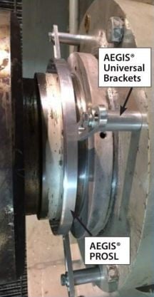
AEGIS PROSLR
The AEGIS PROSLR is specially designed for severe-duty environments and is also available in solid or split-ring versions for shafts of 2.5″ to 16.6″ (63 to 400 mm). To ensure maximum operating reliability in severe environments, an O-ring barrier is installed on its front and back faces to protect it from contamination ingress. The PROSLR has a maximum OAL of 0.750″ (19.05 mm).
AEGIS PROMAX
The AEGIS PROMAX is designed to protect the largest motors and generators. The PROMAX is a split ring for shafts of 16.6″ to 31.5″ (400 to 800 mm) in diameter. Each AEGIS PRO MAX Ring is custom-designed for the specific application, but they all have a maximum OAL of 1.545″ (39.24 mm).
AEGIS PROMR
The AEGIS PROMR comprises a PROSL ring separated by an insulating phenolic spacer from an AEGIS SGR monitoring ring. The PROMR provides both bearing protection and real-time monitoring capability for remote or hard-to-access motors. Available for shafts of 2.5″ to 16.6″ (63 to 400mm), it has a maximum OAL of 1.312″ (33.32 mm).
Universal Mounting Brackets
Universal Mounting Bracket kits speed and simplify the mounting of all AEGIS PRO Rings. They are designed to accommodate shaft shoulders, slingers, and other motor face protrusions.
Don’t risk motor damage and the high cost of lost production. Protect your large motors with AEGIS PRO Series Rings!
For more information on AEGIS PRO Series Rings, click here.
To download a copy of best practice applications for AEGIS PRO Series Rings, click here.
AEGIS Rings also come with a 2-year extended warranty against bearing fluting damage. No other form of protection against VFD-caused bearing damage offers a warranty like this.
To learn more about AEGIS shaft grounding and best practices for electrical bearing protection, sign up for a training. We offer monthly live training webinars, and – pandemic restrictions permitting – we can also visit your facility to review your exact application.