

Author: AEGIS
Cement Maker Protects Bearings With AEGIS PRO Grounding Rings
It seemed as though nothing could stop the squealing. Not that the Monarch Cement Company’s huge ball mill wasn’t already loud. Powered by a 5,000-HP motor, it pulverizes 100 tons of clinker (a burned mixture of limestone and shale) per hour. But the squealing was not what Randy Riebel wanted to hear. As the electrical supervisor at Monarch’s plant in Humboldt, Kansas, he knew the noise meant the motor’s bearings were going — again. In fact, the sound of chronic bearing damage was all too familiar at the plant, which can produce 1.3 million tons of cement a year. Since 2001, when the ball mill was new, its motor bearings have been replaced three times.
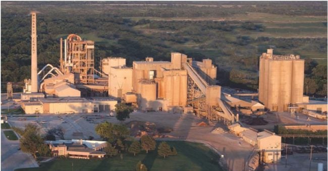
Monarch Cement Company’s plant in Humboldt, Kansas
“We kept greasing those bearings, but they kept on squealing,” Riebel recalls. “We weren’t looking forward to another replacement because of all the expense and downtime. It takes at least ten days to pull that motor — we have to hire help, rent a hoist to put it on a truck and take it away to be rebuilt. So this time [summer of 2009], I decided to try something else.”
 The something else was the AEGIS® PRO Series Shaft Grounding Ring, manufactured by Maine-based Electro Static Technology (EST). By safely channeling harmful electrical current away from the bearings to ground, the PRO Ring extends the lives of medium-voltage motors and generators, thus improving the reliability of entire systems in which they are used.
AEGIS PRO Rings are ideal for medium-voltage motors that drive pumps, compressors, mixers, shredders, conveyors, and other machinery used in mining, food processing, wastewater treatment, petrochemical refining, and many other high-power applications. The PRO Series Ring is available in many sizes, and can protect the bearings of generators, in both utility and on-site power generation systems, as well as motors.
Riebel had been discussing electrical bearing damage with Scott Wilkins, then manager of motor shop operations for Independent Electric Machinery Company (IEMCO), a Kansas City motor and equipment repair contractor. Wilkins recommended the PRO Ring, and Riebel had IEMCO install two of them on the ball mill motor. Riebel chose a split-design PRO Ring, which is optimal for field retrofits. The mating halves of a split AEGISE ring can be installed around the motor shaft without needing to decouple the motor from the mill.
If not diverted, shaft voltage discharges through bearings, pitting the balls and race walls. Concentrated pitting at regular intervals along a race wall without long-term bearing protection can cause washboard-like ridges called fluting, a source of noise and vibration. The eventual result is total bearing failure.
Ironically, some products designed to protect bearings, such as conventional spring-loaded grounding brushes, require extensive maintenance themselves. Others, such as insulation and ceramic bearings, can shift damage to connected equipment.
To improve its conductivity, the PRO Ring’s entire inner circumference is lined with multiple rows of conductive microfibers. Locked securely in the ring’s patented AEGIS FiberLock™ channel, these microfibers surround the motor shaft, providing millions of discharge points for harmful shaft voltage, and create a path of least resistance that effectively diverts these currents away from bearings to ground. The microfibers themselves are specially engineered for exceptional flexibility to prevent breakage and ensure that the ring will last for the life of the bearing. Because it prolongs the life of bearings, motors, and motor-driven systems, the PRO Ring qualifies as sustainable technology under the Federal Energy Management Program.
Contractors and retail home-improvement stores in six Midwestern states depend on the Monarch plant, which sends cement by truck and trains to its terminals in Des Moines, Iowa, and Dodge City, Kansas. When Monarch was founded in 1908, chunks of blasted limestone (“shot rock”) up to four feet across were loaded by hand into mule-drawn carts. This limestone is moved by huge front-end loaders, 50-ton dump trucks, and conveyors to be processed by a series of computer-controlled crushers, kilns, and mills until it is as fine as baby powder.
The problem of chronic bearing damage is not limited to the plant’s ball mills. Many of the motors are controlled by variable frequency drives (VFDs), which induce additional high-frequency voltage on motor shafts. A fan or pump motor tends to use less power if the input is modulated by a VFD, but the benefits of improved efficiency are lost if the motor keeps breaking down.
Such breakdowns were recurring headaches for Riebel, but because the two rings installed on the ball-mill motor were effective, he later had IEMCO install the solid PRO Ring on nine more motors that had to be removed from service. It is now Monarch policy to add the ring in the shop whenever a VFD-controlled fan motor is overhauled.
One example was a PRO Ring installation on the 2,250-HP motor for an induced-draft fan that pulls kiln-heated air through a roller mill, to dry the limestone and shale during the raw grinding process. Other motors that now have PRO Rings include four at the plant’s kilns, where the air is forced in and out: two 2,000-HP ID fan motors and two 1,000-HP bag house (dust-collecting) fan motors.
Using an oscilloscope and a special probe, Riebel periodically checks the motors’ shaft voltage levels. He is pleased with the results because the readings are low, indicating that the rings are providing long-term bearing protection that reduces downtime and maintenance costs.
“So far, so good,” he says. “On the 5,000-HP, since the last set of bearings only lasted a year, chances are we would have noticed problems by now, but we haven’t had any — no squealing.”
At Electro Static Technology, we are so confident in AEGIS Rings that we offer a 2-year extended warranty against bearing fluting damage. No other form of shaft grounding offers a warranty like this.
To learn more about AEGIS shaft grounding and best practices for electrical bearing protection, sign up for a training. We offer monthly live training webinars, and we can also visit your facility to review your exact application.
Pumping Systems on VFD Need Bearing Protection
 In most pump applications, running the pump at full speed is not always necessary. Flow rate has traditionally been decreased with flow control valves, but this has disadvantages. Nowadays, the flow is often controlled by running the pump’s motor on a variable frequency drive (VFD).
Besides well-controlled flow rates, VFDs offer:
• Energy savings (from reduced motor speeds)
• Improved seal and impeller life and reduced vibration and noise (from reduced pressure)
• Greatly reduced water hammer (from smooth acceleration and deceleration)
But VFDs have their own downsides. One big problem is that they create stray voltage on the motor shaft. This shaft voltage can cause electrical damage to motor and pump bearings by discharging (arcing) through them. This electrical damage accrues over time, causing premature bearing failure.
The solution is to electrically bond the shaft to the motor frame with a shaft grounding device. This gives charge on the shaft a low-resistance path to ground, so current flows through the grounding device instead of arcing through the bearings. (Large motors, over 100 hp/75 kW also require one insulated bearing to prevent circulating VFD-induced currents.)
AEGIS® Shaft Grounding Rings are the most reliable form of shaft grounding available. AEGIS rings can be installed on existing motors, and several manufacturers also offer motors with AEGIS rings factory-installed, including vertical hollowshaft, severe duty, and even explosion-proof models.
To learn more about the problem of VFD-induced bearing currents and the solution using AEGIS rings, see these case studies and best practices, or see the AEGIS Youtube channel.
AEGIS Rings also come with a 2-year extended warranty against bearing fluting damage. No other form of protection against VFD-caused bearing damage offers a warranty like this.
To learn more about AEGIS shaft grounding and best practices for electrical bearing protection, sign up for a training. We offer monthly live training webinars, and – pandemic restrictions permitting – we can also visit your facility to review your exact application.
* Image: AEGIS rings being installed on pump motors at Blue Ash Recreation Facility in Blue Ash, OH
Case Study: Electrical Bearing Damage in a Water Treatment Plant
In 2009, the city of Hutchinson, Kansas opened its new Reverse Osmosis Water Treatment Center. The plant uses 17 pump motors, all controlled by variable frequency drives, to move water through the treatment process and to the city’s supply towers.
Electrical Bearing Protection Q&A Part 32
Part 32 in a series of questions and answers from our Q&A webinars.
Q: Is there a spark risk for a dusty sawmill application?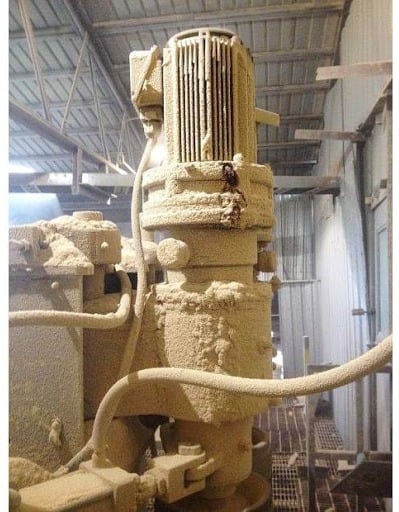
A: An AEGIS® ring mounted on the outside of the motor could increase the risk. It would probably be safe, but “probably safe” isn’t really safe enough.
Instead of mounting outside, it would be best to install the ring inside the motor. Not only for spark risk, but to avoid fouling the ring’s fibers.
Internal installation is one of AEGIS rings’ biggest advantages. Other shaft grounding devices need to be adjusted or replaced; AEGIS is rather a “set & forget” solution. It can be installed in a motor & then not worried about.
Q: In a harsh environment with oil or grease on the shaft, after a while the AEGIS ring gets dirty. How do we get the grease off?
A: It depends how much contamination we’re talking about. The ring would fail if it were flooded, with grease or water or other liquid. In these applications, we highly recommend installing inside the motor. Motor OEMs install rings inside their motors, and motor repair shops also often install rings inside.
As for cleaning: the conductive microfibers can be cleaned with solvents like alcohol or acetone. Some people use gasoline, though we don’t recommend that. Typically, if it’s gotten to the point where you need to clean the ring, we really suggest moving it to inside of the motor.
Other options include external installation with a rubber O-ring on the shaft to screen the fibers from grease. There are also bearing isolators with shaft grounding rings inside, made by Garlock, Flowserve, and AESSeal.
Q: What is the life expectancy of the SGR?
A: The ring’s lifetime is based on the L10 lifetime of a standard rolling element bearing, which is 100k hours for with a shaft of 6″ or less. That’s the ring’s minimum lifetime; lab tests indicate more like 200k hours.
But this all depends on the condition of the shaft surface, and on its size. The larger the shaft, the higher the surface velocity. (The surface of a 6″ shaft moves faster than the surface of a 3″ shaft if they’re both spinning at the same rpm.)
We visited a power plant with 17.5″ shaft at 3600 rpm. In that case, the total distance rate estimated a lifetime of 5.5 years. They were happy to hear that, since they had been using springloaded carbon brushes that only lasted 2 weeks.
Q: What about Class 1 Div 2 environments?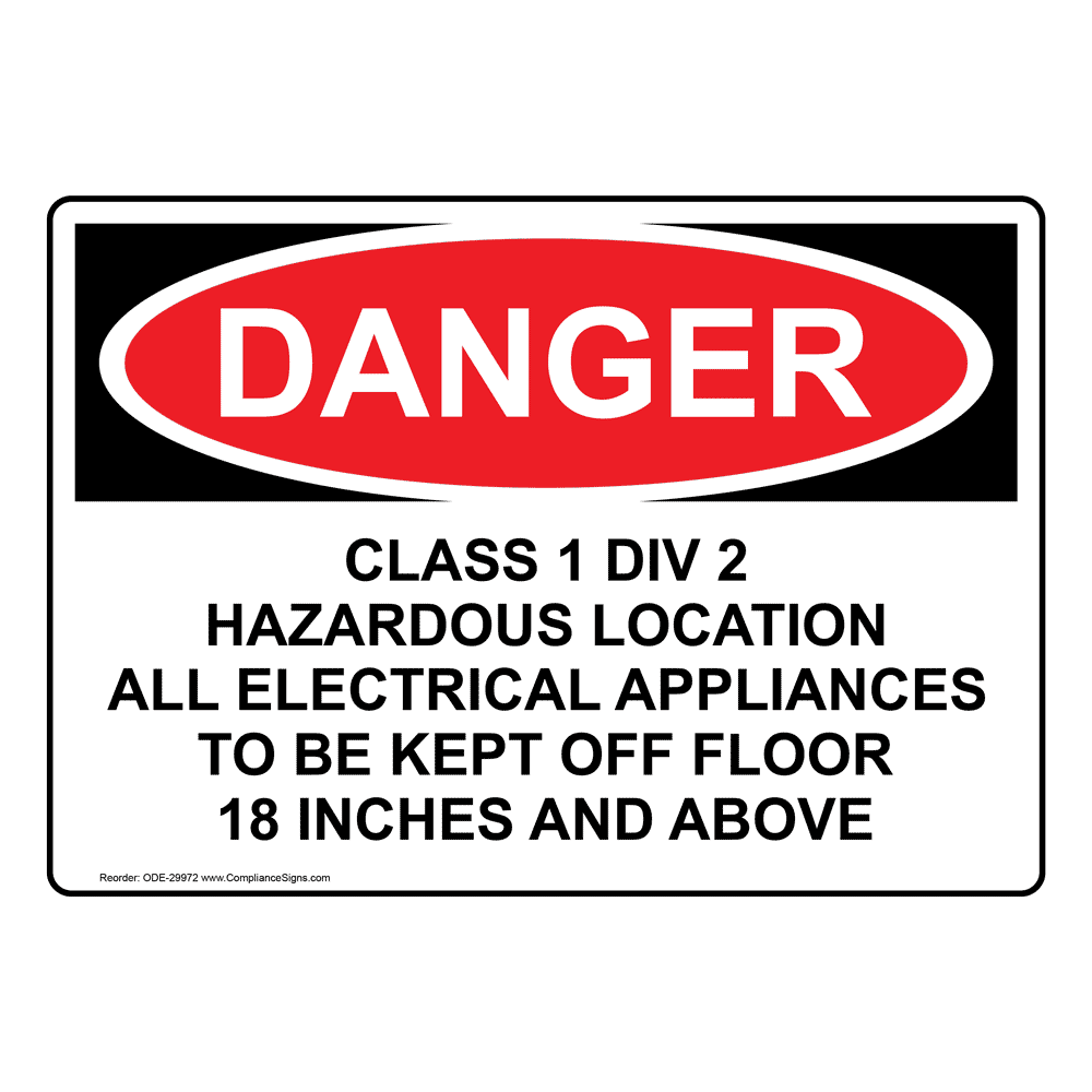
A: All shaft grounding devices are classified as arcing devices. Obviously electrical arcing in a potentially explosive atmosphere is not allowed. Today though, there are motor manufacturers (Marathon (Regal), WEG, & Baldor (ABB)) who offer AEGIS rings installed inside the motor for explosion proof motors for Class 1, Div 1 environments. There are also about 30 different motor repair companies that can install an AEGIS ring in this way, and then nameplate it as Class 1 Div 1-capable.
As for Class 1, Div 2: You can use an XP motor here, though you may not want to go full-on XP. Usually you would use an IEEE-841 motor, a Class 1 Div 2-capable motor. Shaft grounding is allowed in these environments, provided that certain calculations have been done to show safety. You can get the fuller story in this post.
Q: If you’re using a bearing isolator without an SGR, where does the shaft current go?
A: Through the bearings. Bearing isolators prevent contamination from getting into the bearing, but that’s all they do. They don’t protect the bearings from electrical damage, unless they have an integrated AEGIS ring. Again, there are three seal companies that offer seals with integrated shaft grounding rings: Garlock, Flowserve, & AESSeal.
AEGIS Rings also come with a 2-year extended warranty against bearing fluting damage. No other form of protection against VFD-caused bearing damage offers a warranty like this.
To learn more about AEGIS shaft grounding and best practices for electrical bearing protection, sign up for a training. We offer monthly live training webinars, and – pandemic restrictions permitting – we can also visit your facility to review your exact application.
On the Other Side of the Drive: Harmonics and Bearing Currents
An attendee at a recent webinar asked us about electrical bearing damage by harmonic currents created by VFDs. Bearing currents from harmonics are very different from the usual type of VFD-sourced bearing current because they are on the line/supply side of the drive. The bearing currents we normally talk about are on the load side. We don’t talk a lot about harmonics, but we’re happy to explain.
VFDs work by rectifying ac current and storing it in a capacitor bank (the dc bus). Basically, whenever the voltage in a phase is higher than the dc bus voltage, current will flow in to charge the capacitors (Figure 1 – note that in a three-phase system, you actually get two current pulses per voltage peak, but the idea is the same.) This makes VFDs nonlinear loads.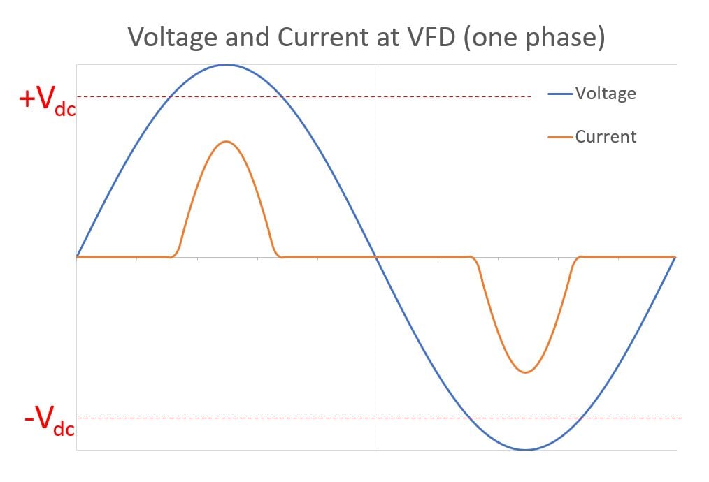
A linear load draws a steady sinusoidal current from the supply. A nonlinear load is any device that does not draw a smooth sinewave of current from the supply. Here’s an analogy: Driving a linear load is like pushing a well-maintained shopping cart. You can push it smoothly along with no jerks or snags. A nonlinear load is like pushing a cart with a sticky wheel that jams every two steps, and you need to shove it to get it moving again. Not smooth.
Nonlinear loads are a problem because they distort the supply voltage and current. Look at Figure 1 again. The drive only draws occasional pulses of current, not a smooth sinewave. If you think of the power supplied by a utility or generator as a large sinewave, drawing out those occasional pulses will put dents in the supply current wave, distorting it. Distorted current in turn distorts the voltage waveform. 
Without getting into Fourier series, you can treat the distortion as being caused by waves with frequencies that are whole number multiples of the supply frequency (50/60 Hz). These higher-frequency waves (at 100/120 Hz, 150/180, etc.) are called harmonics, and they are introduced to the supply by nonlinear loads, including drives.
This causes several problems… upstream of the drive, elsewhere in the facility. Having many drives or other large nonlinear loads in a facility can cause problems not only with other circuits in the facility itself but in other nearby facilities served by the same utility. These problems include interference with sensors; overheating transformers, motors, and generators; and, yes, bearing currents. And again, harmonics generated by one drive can attack motors other than the one controlled by that drive.
Harmonics produce (relatively) low-frequency circulating currents in motors. Like high-frequency circulating currents in larger motors powered by drives, harmonic circulating currents can be mitigated with one insulated bearing. Unlike VFD-caused high-frequency circulating current, they are best mitigated by reducing the supply’s harmonic content. Harmonic mitigation is a field in itself. For a fuller discussion of harmonics and their mitigation, see this newsletter from Trane (Ingersoll Rand) or this presentation from the Power & Energy Institute of Kentucky.
As for this post, the takeaway is that the bearing currents produced by harmonics are separate from what we normally call VFD-caused bearing current. The big difference is that mitigating harmonics will not reduce shaft voltage discharge, high-frequency circulating current, or rotor ground current. For those, you respectively need AEGIS® shaft grounding, an insulated bearing opposite the grounding ring, and good bonding back to the drive or a grounding strap between the motor and load frames.
AEGIS Shaft Grounding Rings also have a 2-year extended warranty against bearing fluting damage. No other form of shaft grounding offers a warranty like this.
To learn more about AEGIS shaft grounding and best practices for electrical bearing protection – for motors and generators – sign up for a training. We offer monthly live training webinars, and we can also visit your facility to review your exact application.
Three Types of Bearing Current: Mitigation
Part 2: Damage Mitigation Strategies
In our last post, we discussed the three types of destructive motor bearing current caused by VFDs: Shaft voltage discharge, high-frequency circulating current, and rotor ground current. This installment discusses a few common methods to minimize VFD-produced electrical bearing damage. As we will see, no one product does it all, but they can be combined to give full protection.
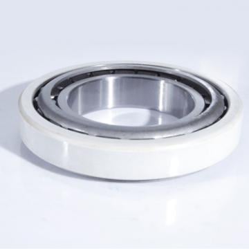
What About Hybrid Bearings?
Hybrid bearings, with ceramic rolling elements, are immune to electrical damage, and insulated bearings with a thin layer of alumina around one race (usually the outer race) are highly resistant. These bearings are electrically robust, but they are also expensive. Another drawback is that, while they block current flow through the motor bearings, they do not protect the bearings of the equipment the motor drives. So you would also need an insulated coupling to protect the equipment bearings. It only takes one insulated bearing to interrupt high-frequency circulating current, though, and this approach can be used in conjunction with other measures against shaft voltage discharge and rotor ground current.
The Best Shaft Grounding Device
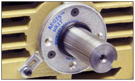 A shaft grounding device provides a low-impedance path between the motor frame and shaft. This disarms shaft voltage discharge and rotor ground current: Rather than arcing through the bearings – a high impedance path – current will flow harmlessly through the grounding device instead. Not all shaft grounding devices are manufactured equally, so choose a long-lived, low/no-maintenance shaft grounding product like AEGIS® Shaft Grounding Rings. However, even the best shaft grounding cannot prevent damage from circulating current, and shaft grounding on a motor cannot protect the driven equipment’s bearings from rotor ground current.
Proper Installation is Critical

High-quality VFD cable, with foil or mesh shielding and symmetrical ground conductors, is the best protection against rotor ground current. Installed properly, it guarantees a low-impedance path back to the drive for stray current. But it is effective only when installed correctly, and does not protect against circulating current or shaft voltage. It can also be quite expensive, especially for long cable runs.
A less expensive, but effective, way to protect against rotor ground current is by bonding the motor frame to the driven equipment frame with special low-impedance grounding straps. With the motor and equipment frames bonded, any stray high-frequency current from the motor frame will move directly to the equipment frame (and then to the ground), rather than arcing through the motor and equipment bearings.
Another approach is filtering the VFD output to eliminate both common mode voltage and current. This is effective, but common mode voltage filters are prohibitively expensive. Most filters, in practice, only filter common mode current. Load reactors, dv/dt filters, and common mode chokes are examples. By reducing common mode current, these filters reduce high-frequency circulating and rotor ground currents. But since they barely affect the common mode voltage, they do not reduce shaft voltage buildup and discharge.
Electrical Bearing Protection Best Practices
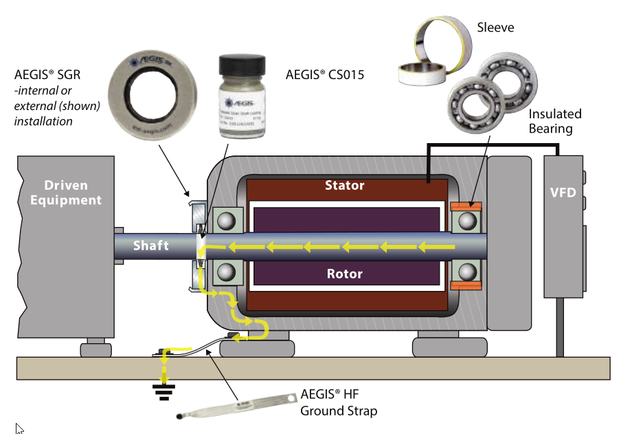 Electro Static Technology has been in the electrical bearing protection business for over 20 years. Our recommended best practices for bearing protection of motors controlled by VFDs are:
- For all motors, use one AEGIS Shaft Grounding Ring (usually at the drive end), to protect against shaft voltage discharge
- For motors over 100 HP (75 kW), insulate the bearing opposite the AEGIS ring (usually the nondrive end), to protect against high-frequency circulating current
- For all motors with uncertain grounding, bond the motor frame to the equipment frame with a high frequency grounding strap, to protect against rotor ground current
These are our recommendations; there are other effective combinations out there. For instance, motors with top-grade cabling would only need an AEGIS ring and one insulated bearing. And you might be able to get full protection from an AEGIS ring and inductive absorbers (common mode chokes). We have not tested all possible combinations; we recommend our best practices because we have tested them and found that they work.
And we are so confident that they work that we offer a 2-year extended warranty on our AEGIS rings. No other form of shaft grounding offers a warranty like this.
To learn more about electrical bearing damage, and best practices to prevent it, sign up for an AEGIS training. We offer monthly live training webinars, and we can also visit your facility to review your exact application.
Changing Standards: Shaft Grounding in IEEE-841 Motors & Hazardous Locations
Shaft grounding for VFD-fed electric motors has largely been disallowed in “Classified” environments where there’s a risk of potentially explosive vapor being ignited. Consequently, many of these motors have been at risk of premature bearing failure due to electrical bearing damage caused by the drive. 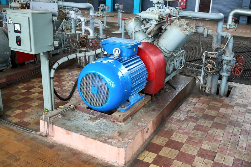
Use of Shaft Grounding Rings in Explosion-Proof Motors
AEGIS® Shaft Grounding Rings have been allowed for years in explosion-proof motors when installed according to UL-approved procedures. Dozens of motor repair companies in the US are qualified to make these installations. Additionally, manufacturers like US Motors (Nidec), WEG Electric, Marathon (WEG), and Baldor (ABB) offer XP motors with AEGIS rings factory-installed. XP motors, though, are usually only used in Class I, Division 1 (Zone 1) areas. In Class I, Div. 2 (Zone 2) areas, where the risk of ignition is lower, IEEE Standard 841 motors are usually used. But until recently, 841 standard motors could not use shaft grounding devices, which are considered sparking devices.
Recent Standard and Code Changes
This began to change with the 2017 edition of the National Electrical Code (NEC; NFPA 70). NEC-2017 allowed shaft bonding (grounding) devices in Class I Div 2 locations, provided “the potential discharge energy is determined to be nonincendive for the application.” In other words, any potential sparks must not have enough energy to ignite the gases present. The 2018 Canadian Electrical Code contained a similar change.
After these changes, the next revision of IEEE Std 841 allowed shaft grounding in 841-compliant motors. This is good news, and not only for users of motors in hazardous areas. 841 motors are used outside of hazardous areas, too. They are built tough enough to endure hazardous areas, and their protective features contribute to a longer life expectancy than less robust motors. So many motor use them by default.
In hazardous areas, the task still remains to calculate the discharge energy. This task got easier in 2021 with the release of IEE Std 1349-2021. The Working Group for this standard also produced a spreadsheet to facilitate calculating the maximum discharge energy based on details of the motor and drive. This spreadsheet is available for free download at the Standard’s webpage (in the Additional Resources section). Although some users complete the calculations themselves, most of the required values are best obtained from the motor and drive manufacturers.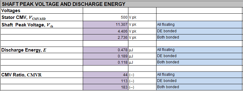
Practically speaking, shaft grounding will usually be permissible in 841 motors in most applications, except when hydrogen (H2) or acetylene (C2H2) gases are present.
For a more detailed review, see our Technical Bulletin.
This is a lot of information, so to summarize:
- IEEE Std 841-compliant motors can now have shaft grounding rings installed in non-classified areas.
- In classified areas, the maximum possible discharge energy must be calculated and ensured to be less than the minimum ignition energy of any potential explosive vapors in the area.
- Users can perform these calculations with input or help from the motor and drive manufacturers.
- Shaft grounding will allow for 841 motors in most situations.
- In cases where shaft grounding cannot be used with 841 motors, explosion-proof motors with AEGIS are still an option.
Partnering with Electro Static Technology
AEGIS Rings offer a 2-year extended warranty against bearing fluting damage, in or out of hazardous locations. No other shaft grounding device manufacturer offers a warranty like this.
To learn more about AEGIS shaft grounding and best practices for electrical bearing protection, sign up for a training. We offer monthly live training webinars, and we can also visit your facility to review your exact application.
Three Types of Bearing Current: Causes
Part 1: The Problem
Variable frequency drives are often used to control three-phase electric motors. Drives allow precise control and sometimes large energy savings but also damage motor bearings. This is widely accepted but little understood. In this article, we will try to shed some light on the three ways drives cause electrical bearing damage. In the next installment, we will talk about how each of these modes of damage can be mitigated.
First, some background: Line voltage and current are sine waves at 50 or 60 Hz, depending on the country. With three-phase power, the voltage is balanced. The sum of the three-phase voltages is zero. They cancel each other out, so the line, and the motor, are neutral overall. When a motor is run on line power, its speed is determined by the line frequency. 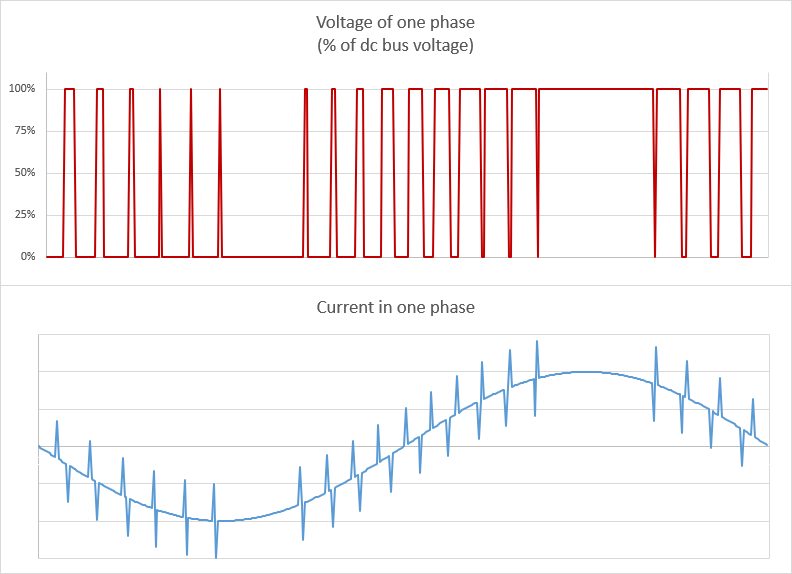
VFDs convert line power into a series of pulses of voltage in each phase, shown in the top of the figure. By controlling the timing of each pulse, the drive can run the motor at speeds much slower than the line frequency. But unlike line voltage, the drive output voltage is not balanced. The pulses in each phase do NOT cancel each other. Their sum is called the common mode voltage (CMV).
The current from a drive looks less like a pulse and more like a sine wave. But every time the drive switches on or off, there is a spike in high-frequency current. Between the three phases of drive power, the current mostly cancels out. Except for those spikes. The sum of the current spikes in each phase is called the common mode current, which we’ll abbreviate CMC.
Before moving on to the motor, it’s worth discussing the relationship between the voltage and current in each phase. The spikes of current are caused by large rapid changes in voltage from the drive. The rate of voltage change is called dv/dt. dv/dt is always large for modern drives because their switching is very fast. With a low-voltage drive, the voltage changes by hundreds of volts in under a millionth of a second. Medium voltage drives have even larger voltage changes in similarly short intervals.
When the drive’s output wave reaches the motor, two things happen. First, the CMV electrostatically charges the rotor. If the windings are positive, this will attract electrons (negative) to the middle of the rotor, leaving a positive charge at the ends. This produces a voltage across the bearings, which can be measured as the shaft voltage. If the shaft voltage builds up high enough, it will arc through the bearing, damaging the balls and raceways. This shaft voltage discharge is often called rotor discharge current or EDM current, and is shown in yellow in the second figure. EDM current may peak between half an amp to a few amps. It is a problem in all motors on drives, regardless of size. In small well-grounded motors, this is only damaging bearing current that drives cause.
Rotor discharge current depends mainly on the size of the CMV, not its rate of change. If dv/dt is decreased, the shaft voltage will increase less rapidly but will still reach the same peak value. If the peak voltage is high enough to cause arcing through the bearing, the damage will still be done.
Meanwhile, the high-frequency CMC leaks through the capacitance between the stator windings and the frame to seek a low-resistance path to ground/back to the drive. (The windings have high inductance, which means high impedance for high-frequency current.) This can also be described as the high dv/dt charging stray capacitance in the motor frame. Regardless of the terminology, this has two potentially damaging consequences.
In large motors, over 100 hp/75 kW, the CMC induces high-frequency circulating current. This current flows from shaft to frame through one bearing (orange) and back to the shaft through the other bearing (at right). This current’s mechanism is more complicated. Basically, as it runs to ground, the common mode current is not evenly distributed over the motor. This produces an unbalanced magnetic flux inside the motor. Electrons in the rotor and frame will “try” to circulate to counteract that flux. The resulting high-frequency circulating currents’ size can range from a few up to 20 amps.
The other side effect of CMC occurs in motors poorly grounded/bonded to the VFD. If the motor frame does not have a low-impedance path to ground, then the CMC can arc through the motor bearings, run down the shaft, through the coupling into the load equipment, arc through that equipment’s bearings, and then run to ground. This is called rotor ground current (blue). (Some sources confusingly call it shaft grounding current.) Rotor ground current can be several tens of amps, and is doubly destructive because it damages both the motor and the equipment bearings.
Both high-frequency circulating current and rotor ground current is caused by common mode current or, equivalently, the common mode voltage’s large rate of change.
Fortunately, all of these destructive bearing currents can be brought under control. In this sequel post, we discuss mitigation strategies for each.
To learn more about AEGIS shaft grounding and best practices for electrical bearing protection, sign up for a training. We can visit your site and give an in-person training with an emphasis on your specific focus. We also offer monthly live training webinars.
AEGIS Shaft Grounding in Wind Turbine Generators
Along with solar power, wind power is the fastest-growing renewable energy source. Wind turbine generators work by capturing energy from the wind and using it to spin the generator shaft, producing electric power. These generators use a gearbox and an inverter drive (a.k.a. VFD) to match the power output’s frequency to grid power’s 50 or 60 Hz. Most also use inverters to excite the generator, while others use permanent magnets.
VFDs, Stray Voltage, and the Generator Shaft
But VFDs also create voltage on the generator shaft. This voltage will discharge to ground by any available low-resistance path. Unfortunately, these paths usually lead through the generator or gearbox bearings. Discharge through these moving parts causes cumulative electrical discharge machining damage. In bearings, the damage is called fluting; in gearboxes, it’s called tiger-striping. Whatever you call it, electrical damage causes generator failure. And failure means expensive repairs and downtime.
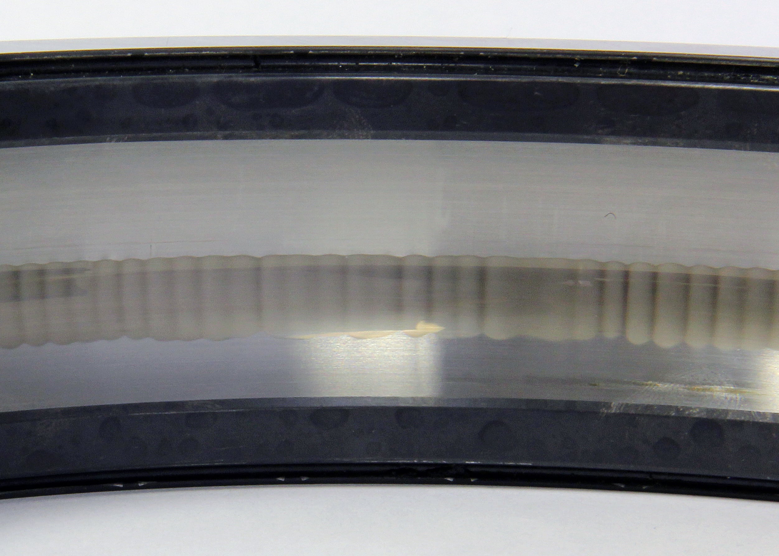
Wind Generator Electrical Bearing Damage
Most generators have hybrid or insulated bearings that resist electrical damage from discharge and circulating currents. But coupled equipment, like gearboxes and tachometers, is left vulnerable. So wind generators also include rotor grounding to reduce the risk to this equipment. Inverter-excited generators use a carbon shaft grounding brush, and permanent magnet designs use rollers on the brake disk. Both methods provide a low-resistance path to low-frequency and DC current. So this otherwise destructive current goes harmlessly through the brush or roller.
But shaft voltage contains high and low frequencies, and brushes and rollers have high impedance (resistance) to high-frequency electricity. So even with a brush or roller, the system is still at risk of electrical damage. Wind turbine generators also need a form of shaft grounding with low impedance at high frequencies.
Does a Wind Turbine Need Shaft Grounding?
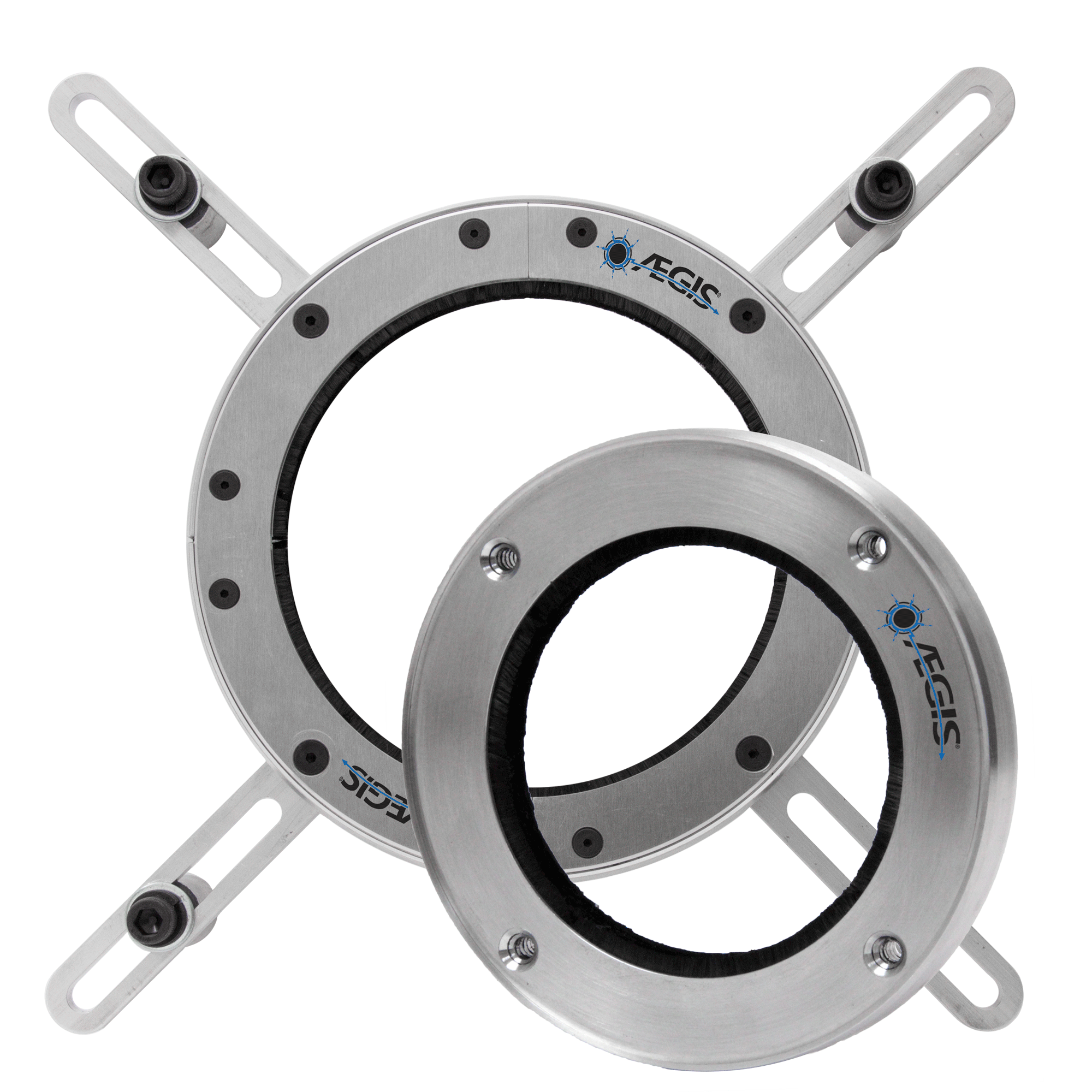 The short answer is yes, and AEGIS® Shaft Grounding Rings are part of the solution. AEGIS PRO Series Rings surround the shaft with hundreds of thousands of conductive microfibers. These fibers have a high surface area, which gives them low impedance to high-frequency current.
With hybrid bearings to block circulating currents, a roller or carbon brush to carry dc and low-frequency current, and an AEGIS Ring for high frequencies, the system is fully protected against electrical bearing damage.
In the Field: Testing for a Wind Generator Manufacturer
Jens Leipner, the AEGIS Sales Manager for Northern Europe, recently went up-tower to do testing for a wind generator manufacturer. The test site was a 455-foot tall turbine (140m) turbine with 440-foot blades. The generator itself was a permanent magnet/VFD model. It had rollers on the brake disk for low-frequency grounding and a “violin string” shaft grounding device for high frequencies.
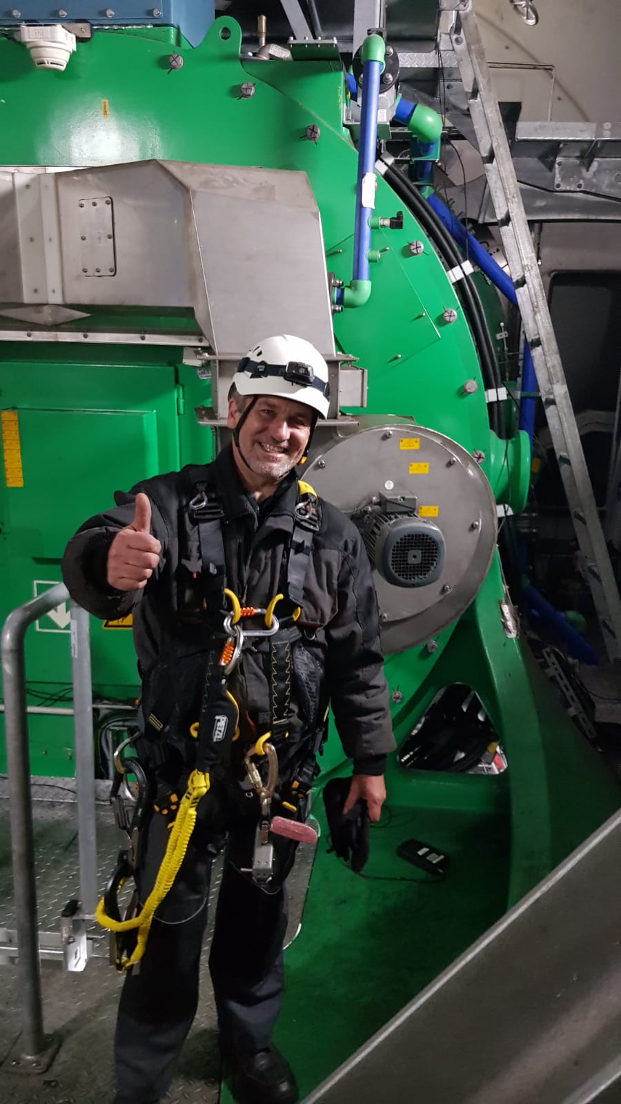
With no shaft grounding, the shaft voltage was 20 volts peak to peak. With the shaft grounding string, the voltage was brought down to a little over four volts. This is a safe level, but the grounding string showed severe wear. Because these devices are pressed, under tension, against a spinning shaft, they can quickly wear through.
When AEGIS PRO Ring segments were installed, the shaft voltage was decreased to safe levels of less than a volt. Further, the AEGIS Ring’s fibers are not under tension; they only press lightly against the shaft. This makes them much longer-lived than grounding strings.
With long lifetimes and low impedance at high frequencies, AEGIS grounding rings are wind turbine generators’ most effective grounding systems for high-frequency shaft voltage.
AEGIS Rings also come with a 2-year extended warranty against bearing fluting damage. No other form of protection against VFD-caused bearing damage offers a warranty like this.
To learn more about AEGIS shaft grounding and best practices for electrical bearing protection, sign up for a training. We can visit your site and give an in-person training with an emphasis on your specific focus. We also offer monthly live training webinars.
AEGIS Shaft Grounding Protects Generator Gearboxes
Updated: February 2024
People usually have AC motors in mind when talking about shaft grounding. But a generator is just a motor running in reverse. In a motor, external electric power forces the rotor to spin. The input and output are reversed in a generator: an external source spins the rotor, producing electric power.
The High Stakes of Unprotected Equipment
Motors and their coupled equipment are vulnerable to electrical bearing damage. And so are generators and their peripheral equipment. On land, this damage can lead to unplanned downtime and colossal loss of income. But if a sea vessel’s generator or gearbox fails, the ship may be left dead in the water.
Real-World Impact: A Case Study
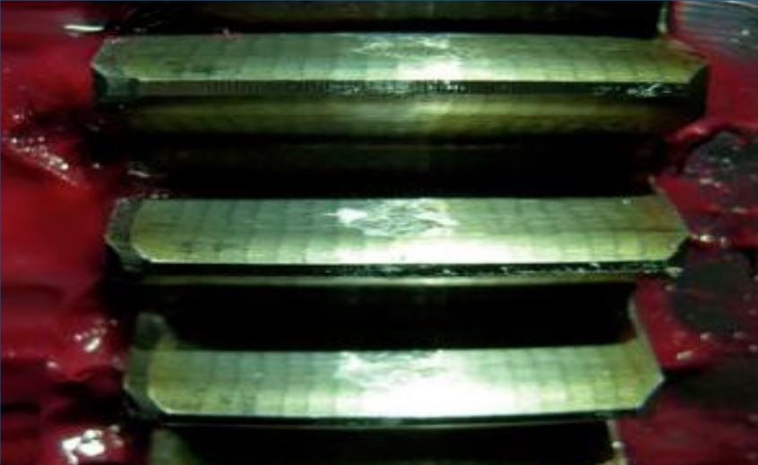
This happened to a commercial ship when the auxiliary reduction gears that drove its generator suddenly failed (pictured). Without the gearbox, the 1.5 MW generator couldn’t run, and without the generator, the ship had no electricity. The ship had to return to Shanghai for gearbox repairs. The cause was electrical arcing through the gearbox. Every day’s delay cost the owners $10,000, so they had to solve this electrical problem quickly.
They called in Xview Asia, a Hong Kong-based electrical supplier. Xview found that the generator created high-frequency voltage waves that traveled down the input shaft to the gearbox. There, they discharged to ground by arcing through the gears and bearings. This type of shaft voltage would normally cause circulating currents within the generator, from shaft to frame and back. But the generator’s bearings were insulated. This protected the generator from bearing damage but left the voltage to seek another path between the shaft and frame. The path it found was through the gearbox to ground.
Insulating the gearbox’s bearings would not solve the problem because the gears would still be vulnerable. But grounding the generator shaft could give the shaft voltage a low-resistance path to ground. Rather than arcing through the gearbox, the voltage would bleed off harmlessly through the grounding device. So Xview tried using carbon brushes to ground the shaft, but they only reduced the maximum voltage from 5.5-6.5 volts to 4.5 (peak to peak). Carbon brushes are good at conducting direct current but much less good at conducting high-frequency alternating current.
Expert Intervention with AEGIS® Solutions
So Xview then tried an AEGIS® PRO Shaft Grounding Ring. AEGIS Rings are designed to offer low resistance to high-frequency AC electricity. With the PRO Ring installed, shaft voltage was reduced to much lower levels, under 2 volts. Problem solved.
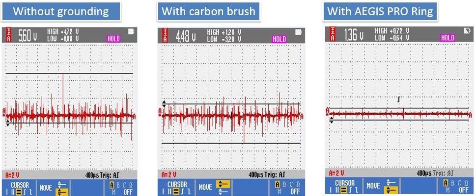
Generator shaft voltage without shaft grounding, with carbon brush, and with AEGIS PRO Ring
The cost to repair the gearbox was over $1 million. The owners were very eager to avoid this kind of damage in the future. Because the PRO solution was so effective, they installed PRO Rings on four other ships in their fleet.
Choose Reliability. Choose AEGIS®
In the face of potential electrical bearing damage, trust in the proven performance and industry-leading expertise of AEGIS®. Elevate the reliability and longevity of your motor-driven systems by embracing the unparalleled protection offered by AEGIS® Shaft Grounding Rings.
AEGIS Rings also come with a 2-year extended warranty against bearing fluting damage. No other form of shaft grounding offers a warranty like this.
 To learn more about AEGIS shaft grounding and best practices for electrical bearing protection, sign up for a training. We offer monthly live training webinars, and we can also visit your facility to review your exact application.